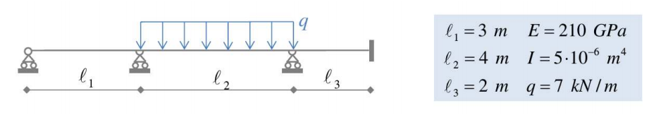
In this page we want to show you how to create the model of a continuous beam on several supports like the one shown in the figure. You can check it now in WeStatiX if you want! You can find it among the tutorials.
Step by Step
GEOMETRY
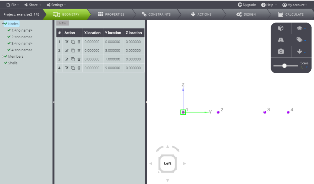
First, you have to create the nodes. The coordinates are:
- 1: ( 0 ; 0 ; 0 )
- 2: ( 0 ; 3 ; 0 )
- 3: ( 0 ; 7 ; 0 )
- 4: ( 0 ; 9 ; 0 )
Click on the GEOMETRY tab and then Node in the Entity tree.
Move to the Data Panel and click on New, then enter the coordinates of the first node in the X location, Y location, Z location fields.
Repeat the operation for all nodes.
Create members, from graphical interface or by typing in the Data panel.
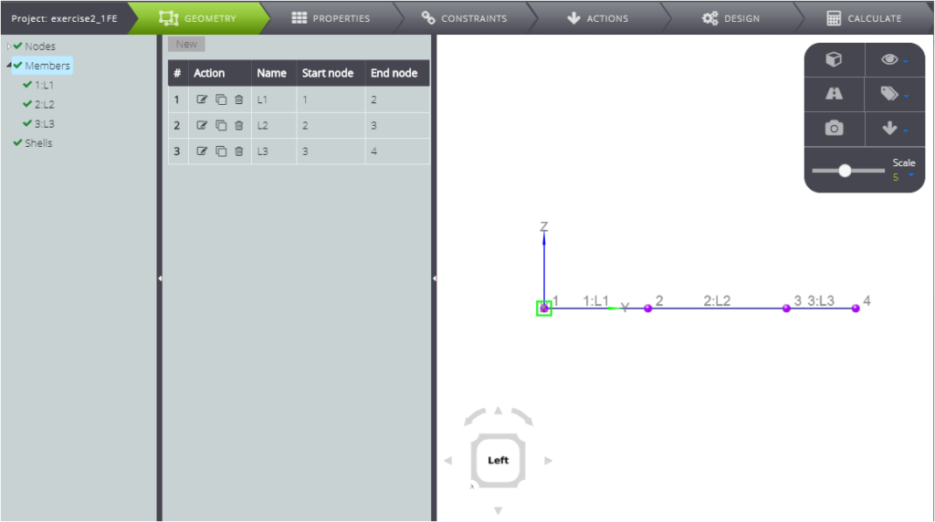
Now define the properties!
PROPERTIES
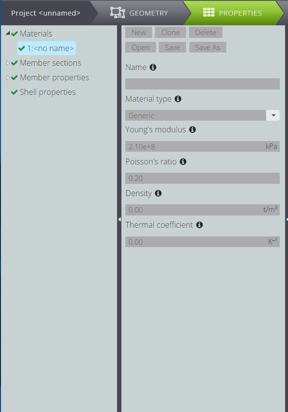
Click on PROPERTIES in the top bar, and start defining the material.
Click on New, then fill in the fields as you see below.
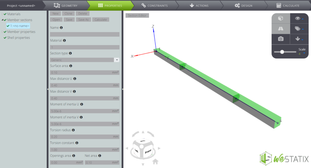
In the same way, you can generate the section with the data parameters.
Click on Member Sections in the Entity Tree and then New in the Data Panel.
Fill in all fields as below.
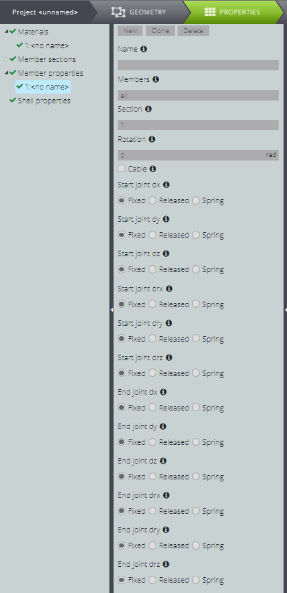
The beam is continuous (so each span is stuck with the previous one) and you won’t need to impose internal constraints between the various elements that make up the model. You can assign properties to them exactly as shown in the figure below.
To open this window, simply press Member propierties in the Entity tree and New in the Data panel.
CONSTRAINTS
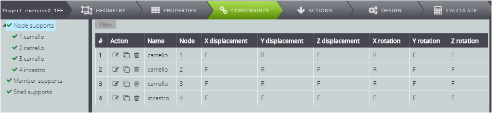
Now impose external constraints. Move to the CONSTRAINTS tab and then click Node supports. Generate four new constraints in the Data panel and tick the degrees of freedom you want to free or block.
In the summary table of the image below are marked with F (fixed) the blocked degrees of freedom and with R (released) the unbound degrees of freedom.
Now you are only missing loads!
LOADS
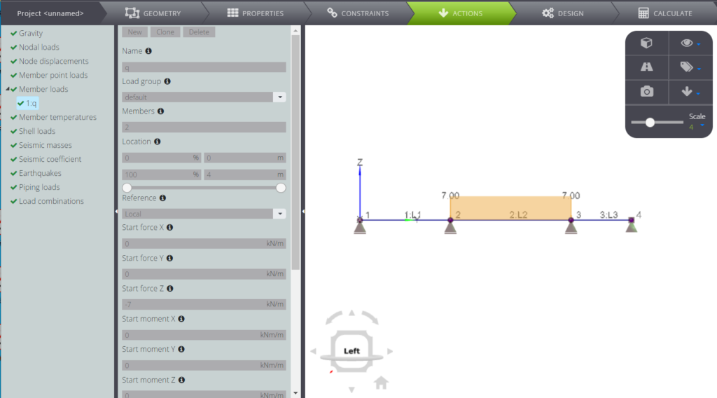
Go to ACTIONS and select Member loads in the Entity tree.
Enter 2 in the Member field, and then the load amount in the Start force Z and End force Z fields.
ANALYSIS & RESULTS
Ready to launch the analysis? Press CALCULATE and then Start calculation in the Data Panel.
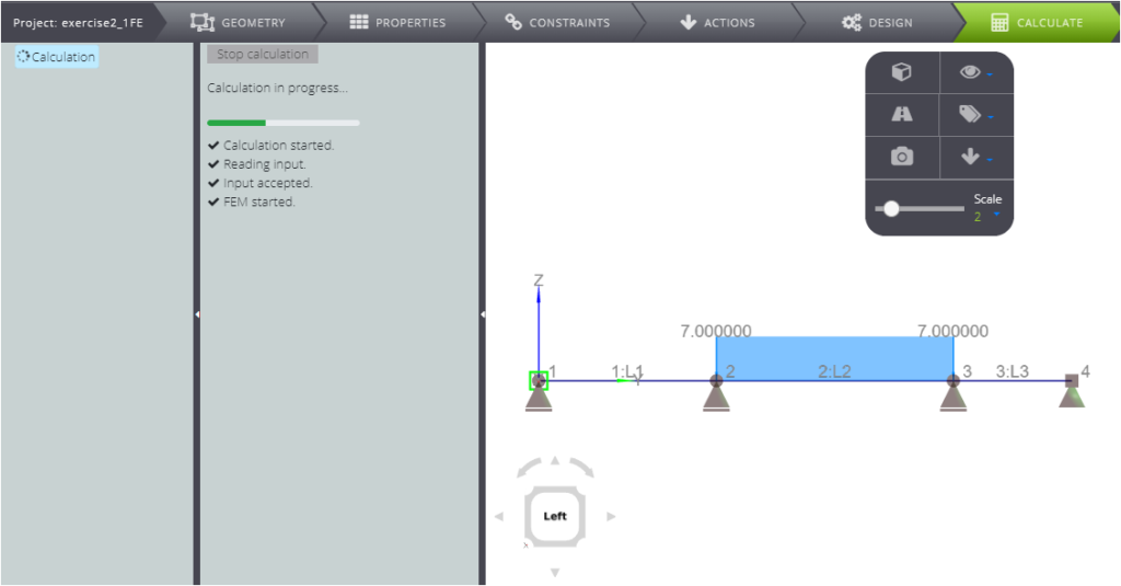
When the results are ready, you can choose in the Entity tree what you want to see!
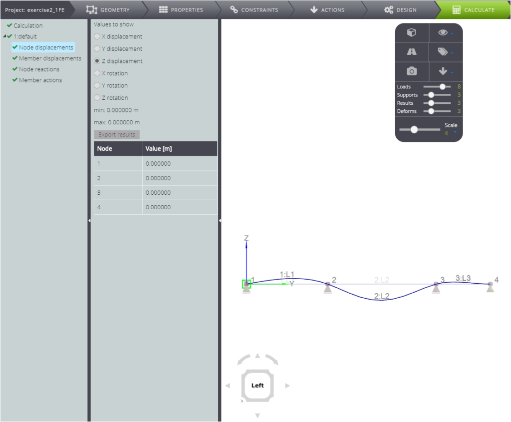
Below you see the system deformation.
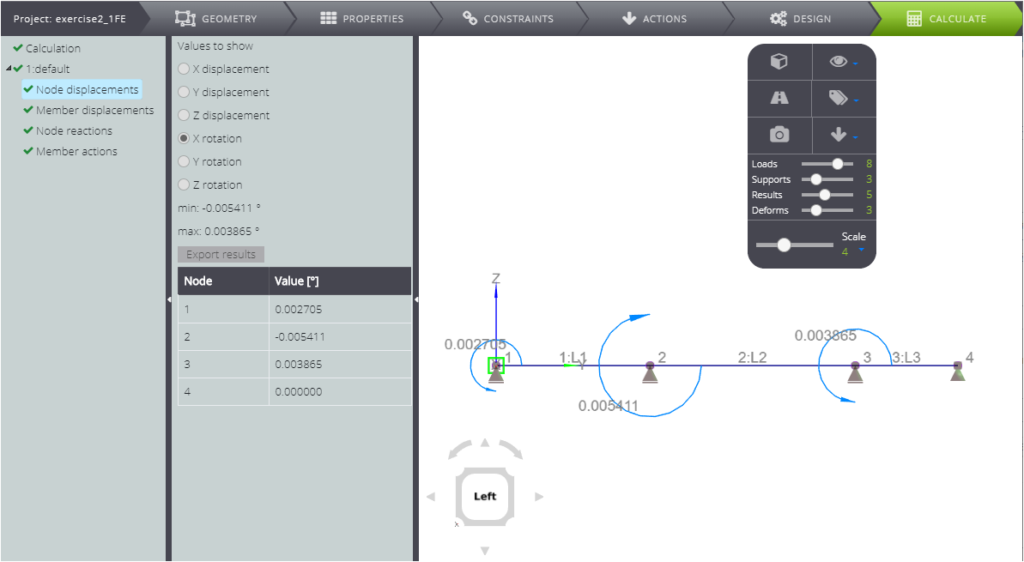
The rotations of the nodes around the X axis,
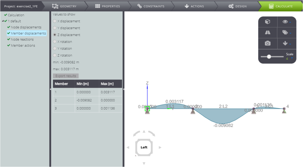
The displacement of members in the Z direction.
Remember that if the results don’t have the shape you expect, it could be because of the mesh settings! We also did this in the example of a cantilever beam.
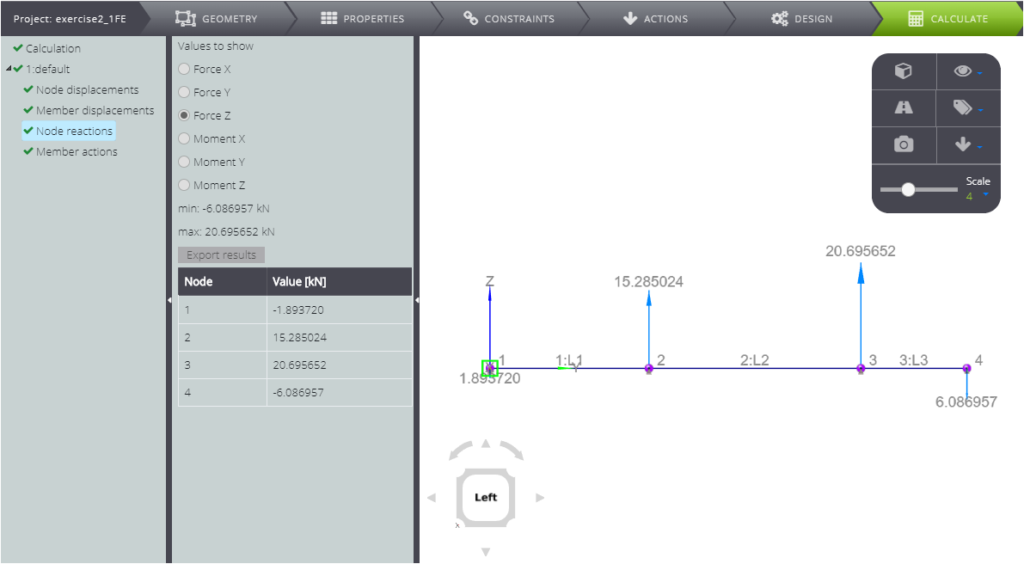
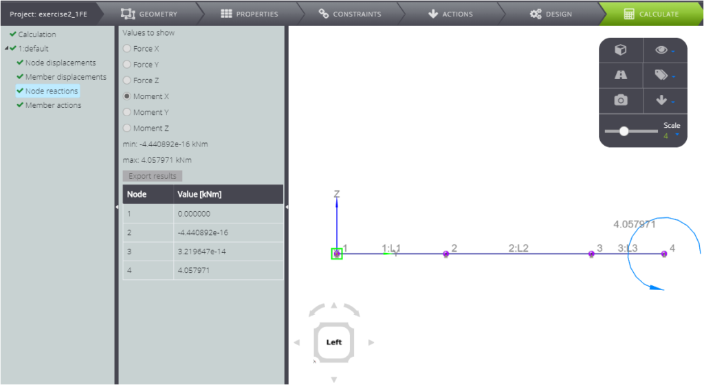
In the results you will also find the binding reactions
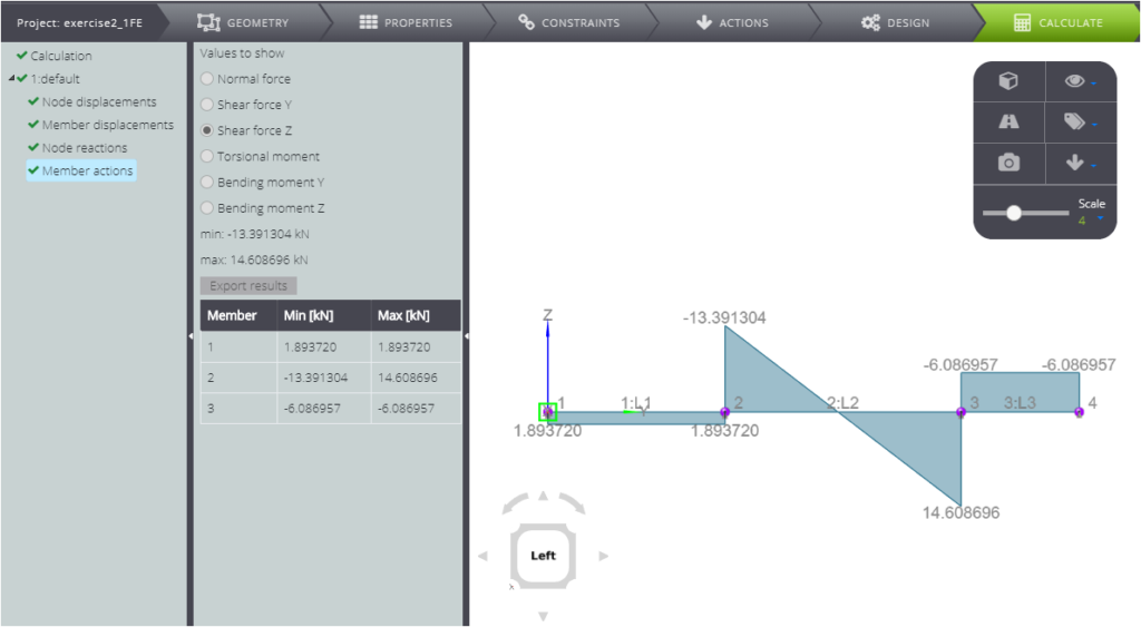
At last, you can read the diagrams of internal forces, such as cutting, as shown below…
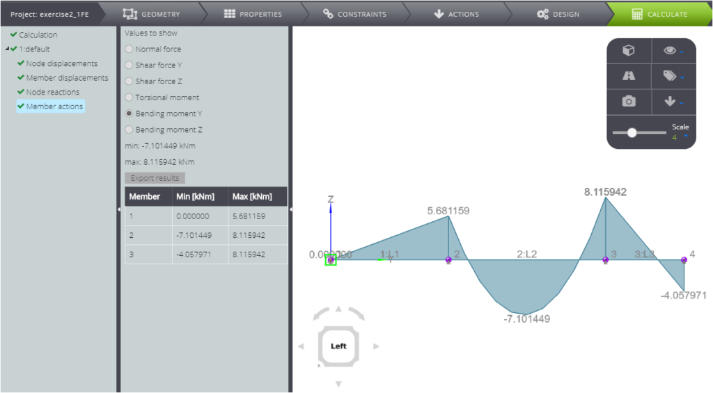
…and the bending moment!
Results are commented and compared with the analytical solution in the Validation Manual.