On this page you can read how to create the system model shown in the figure below. It is a continuous beam with elastic support in C.
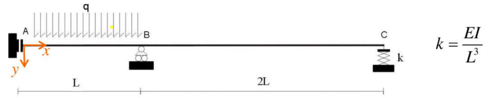
You can also find it among the tutorials saved in WeStatiX.
Step by step
Follow the workflow on the Tab Bar to define all elements of the model.
GEOMETRY
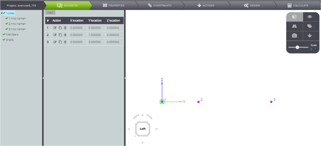
Follow the Tab Bar and press on GEOMETRY, and start creating the nodes.
The coordinates are
- A: ( 0 ; 0 ; 0 )
- B: ( 0 ; 1 ; 0 )
- C: ( 0 ; 3 ; 0 )
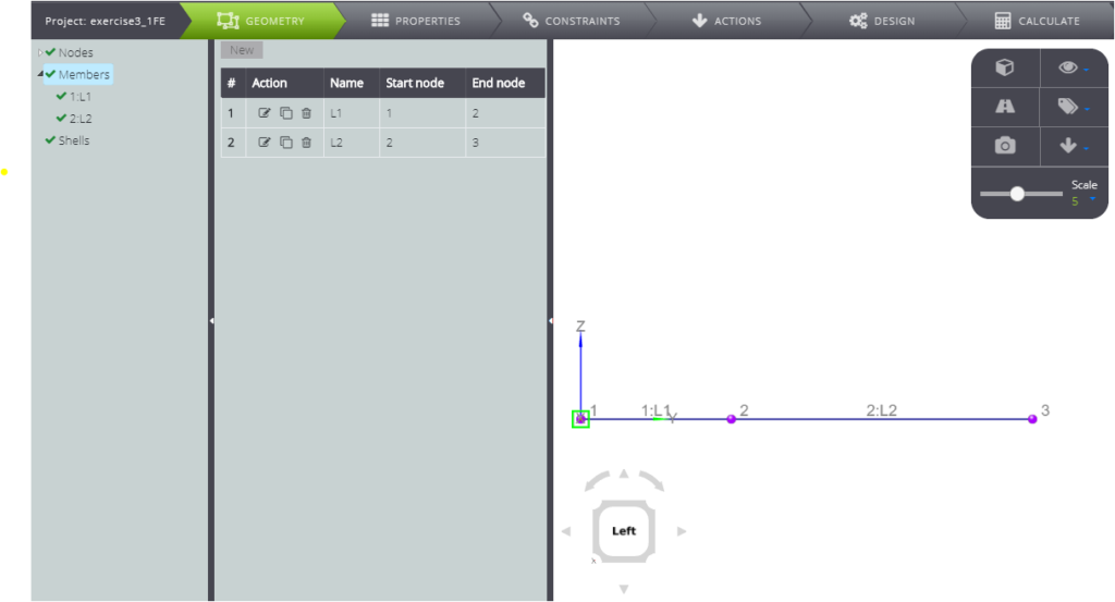
When you are done, create members.
PROPERTIES
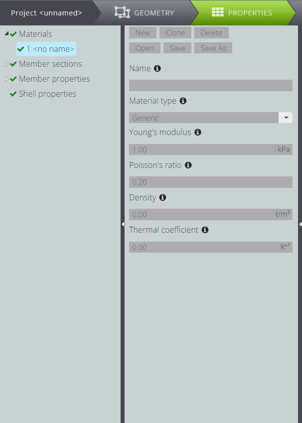
Now you can generate all properties related to your model. Move to PROPERTIES and define the material.
Then define the parametric section. If you press Section Editor, it will open and you can see your section.
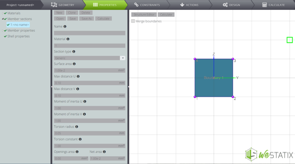
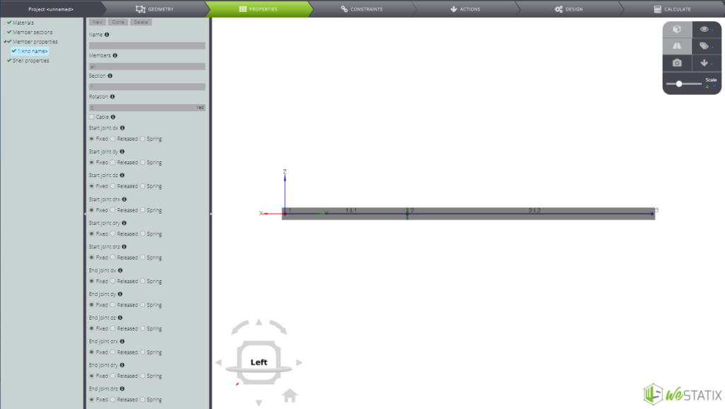
Now attribute the features to the members you created. Inside the Entity tree move to the member section and fill in all the fields as in the image below.
Constraints
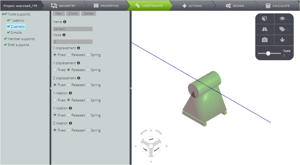
Then define the external constraints. Click on CONSTRAINTS and define them according to the following summary table.
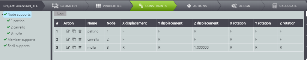
First of all, for the node in A let the vertical displacement free.
Secondly, for the node in B release the rotation around X and the sliding along Y.
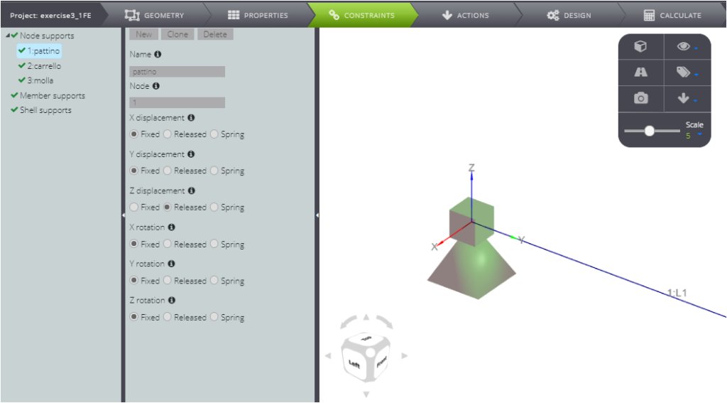
Lastly, for the node in C release all degrees of freedom with the exception of the sliding along Z, where you want to impose a sagging constraint:
- select Spring in the Z displacement field
- enter a value of elastic constant equal to 1 kN/m in the field that appears.
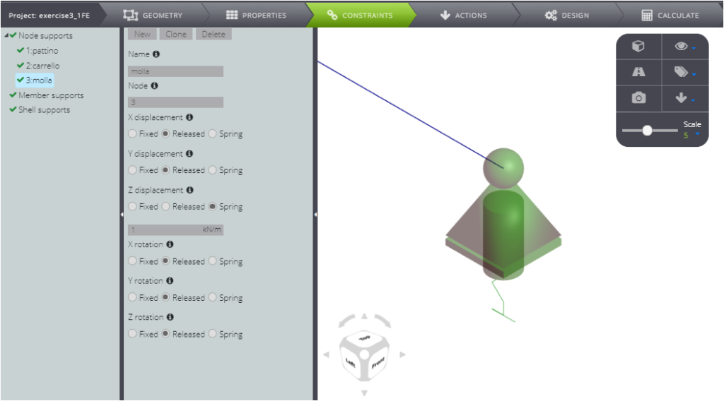
This is how you defined the elastic support for the continuous beam.
ACTIONS
After defining the constraints, impose the load. Press ACTIONS and insert a uniformly distributed load of 1 kN/m over the entire length of member 1.
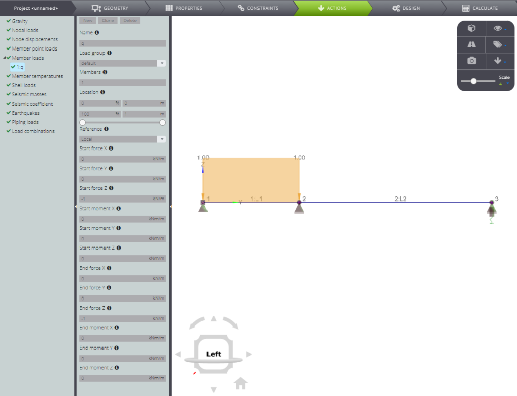
Are you done? Start the analysis!
ANALYSIS AND RESULTS
Click CALCULATE and then Start calculation.
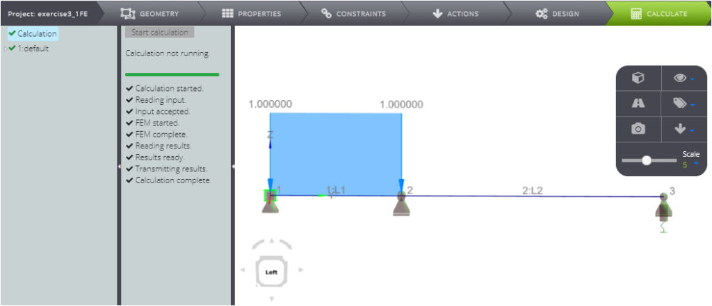
Scrolling below 1:default you can see all results
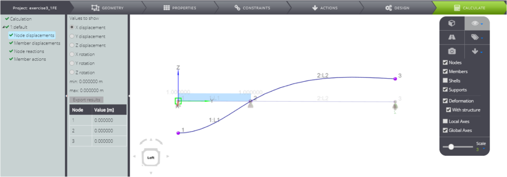
More specifically:
- nodal displacement
- elements displacement
- nodal forces
- internal stress parameters
You can also find it in our Verification manual, where you can compare the numerical and analytical solution.