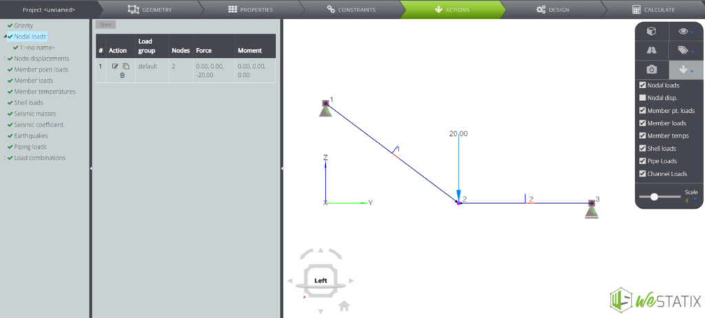
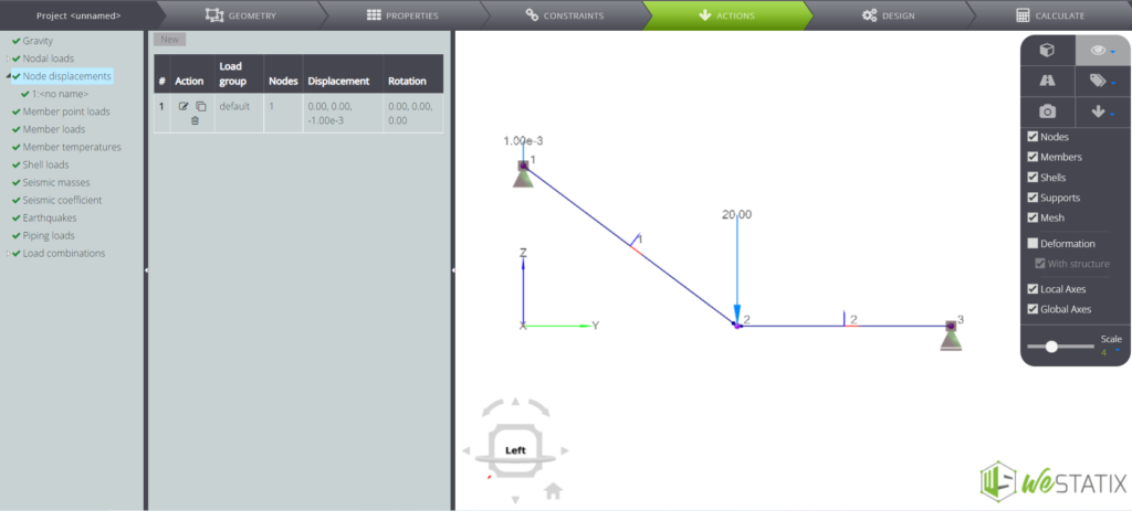
In this page we see how to create the model of the system represented in figure: note that in A is imposed a vertical displacement.
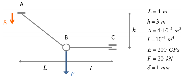
The model has already been created in WeStatiX: you can find it among the tutorials.
GEOMETRY
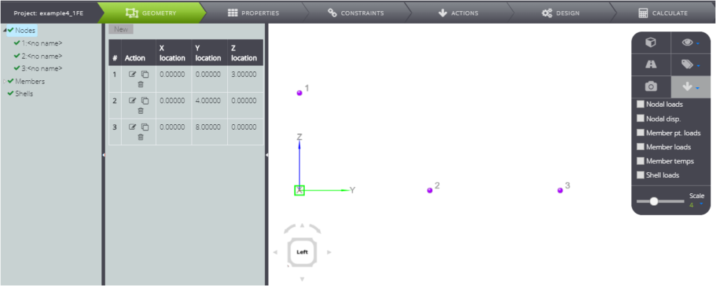
First of all, create the nodes! You can create them directly in the Viewport 3D by double tapping on the grid points.
The coordinates are
- 1: ( 0 ; 0 ; 3 )
- 2: ( 0 ; 4; 0 )
- 3: ( 0 ; 8 ; 0 )
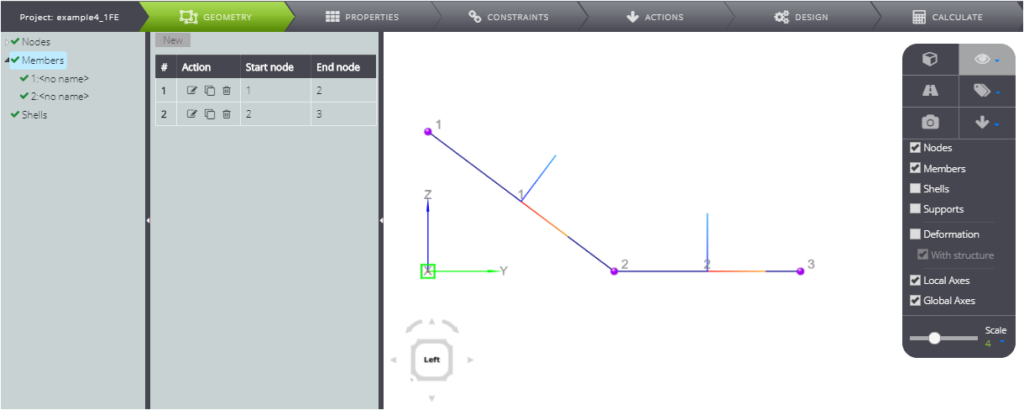
To create members, you can continue to act manually in the Viewport 3D:
- press once on node 1 and twice on node 2
- press once on node 2 and twice on node 3
In this way you created member 1 and member 2 in sequence.
PropERTIES
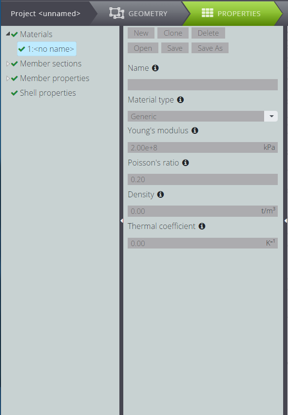
Now go to the PROPERTIES Tab to define the properties.
Create a parametric material by following the Materials, New path and filling in the fields as in the image below.
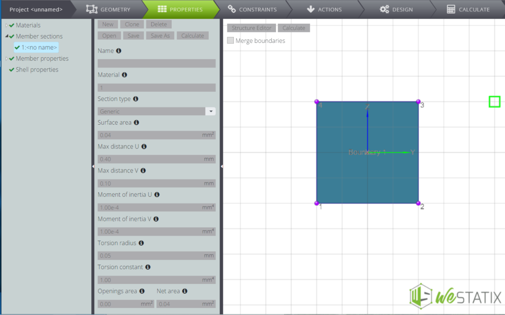
In the same way, following Member sections, New, you can enter the parameters of the section. Activating the Section Editor you can see it represented.
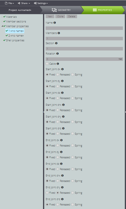
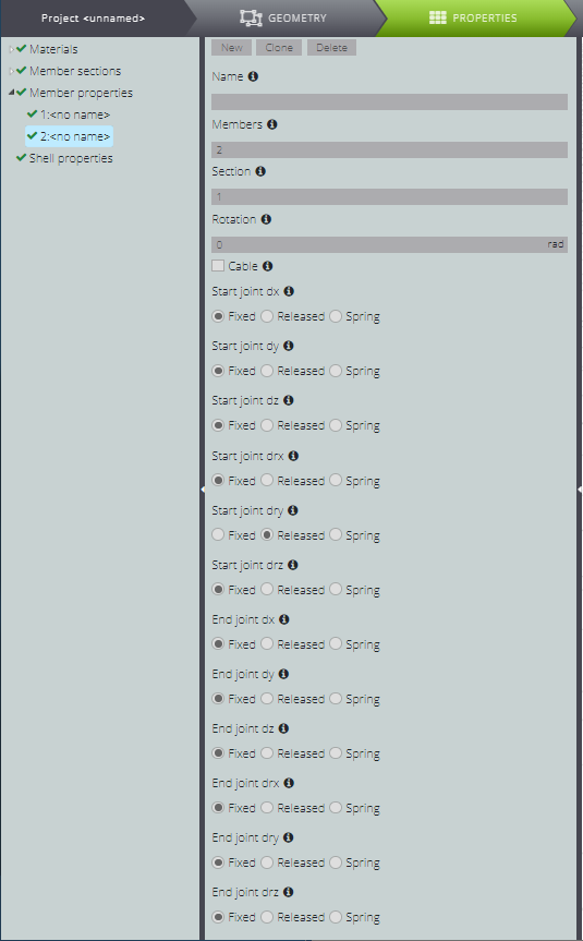
Now attribute the properties to the two elements as shown in the table below.
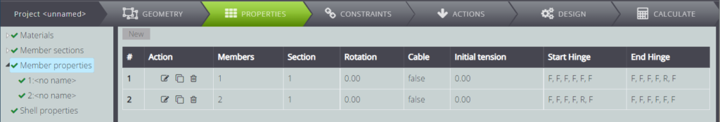
For member 1, in particular, you will have to free the start rotation around the y-axis to create the inner hinge.
For member 2 as well, you will have to free the end rotation around the y-axis to create the inner hinge.
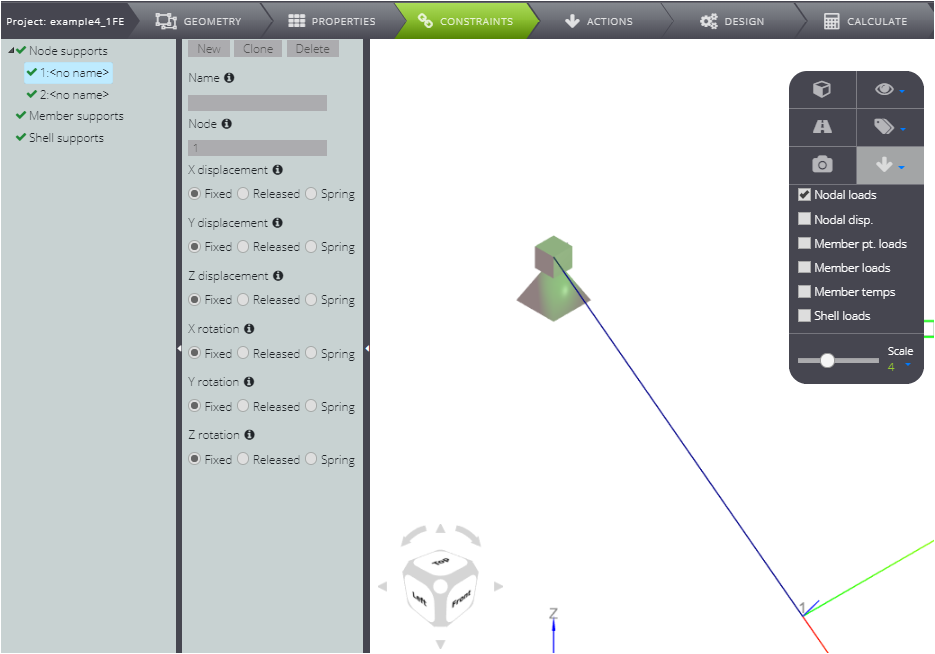
CONSTRAINTS
Now generate external constraints! Find their characteristics summarized in the table.
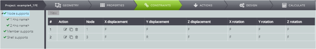
In particular, for node 1 leave all degrees of freedom locked to create a joint.
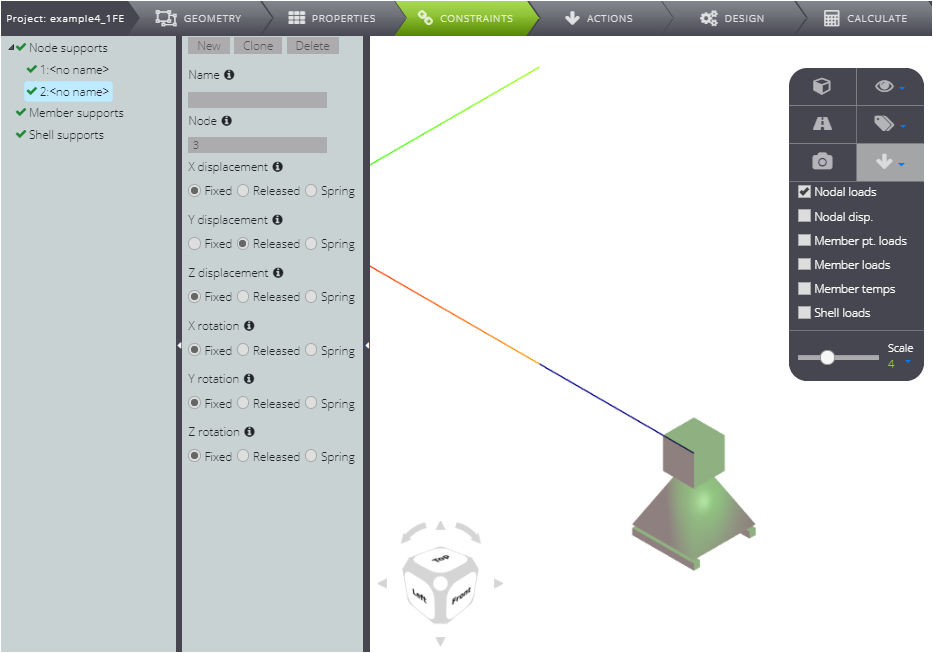
In node 3, on the other hand, free the scrolling along Y.
loADS
Now go to the definition of the loads on ACTIONS.
On Node loads impose a vertical load at node 2.
Type -20kN in the Force Z field.
In the same way impose vertical bind failure for node 1.
Create a new case on Node displacements, then type -1mm in Z displacement.
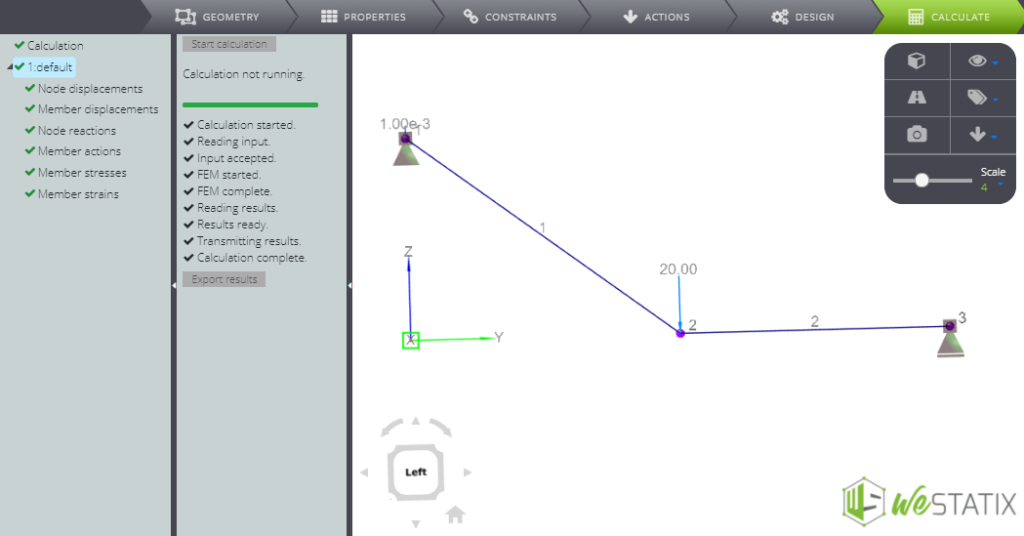
ANALYSIS & RESULTS
You have finished the model! Press CALCULATE and Start calculations to get the results.
When you have finished the analysis, you can consult
- nodal displacement
- members‘ displacement
- binding reactions
- diagrams of the stress parameters.
We used this model in the Verification manual: here you can find the comparison between the numerical and the analytical solution.