Do you want to create this system in WeStatiX? Here we explain how to do it, but you can find it among the tutorials in WeStatiX.
GEOMETRY
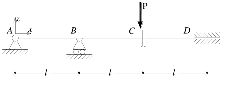
Follow the Tab Bar and select GEOMETRY.
Create nodes first: you can do it by typing in the Data Panel or by clicking on the grid points in the Viewport 3D, whichever you like best!
The coordinates are:
- 1: ( 0 ; 0 ; 0 )
- 2: ( 0 ; 1 ; 0 )
- 3: ( 0 ; 2 ; 0 )
- 4: ( 0 ; 3 ; 0 )
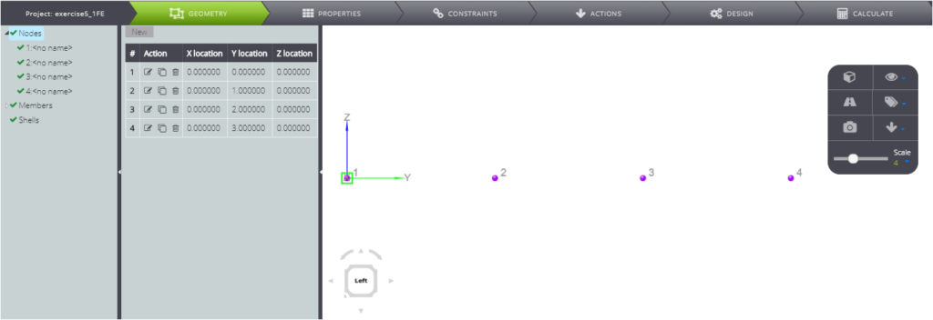
Immediately afterwards you can quickly create member elements.
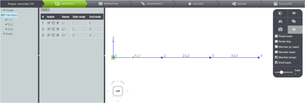
PropERTIES
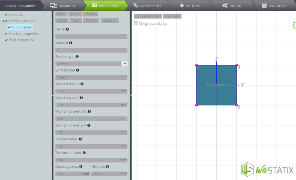
You can then move to PROPERTIES and define the properties of the parametric material
…and section.
Now pay attention when assigning properties to the various members.
Below you will find the summary table.
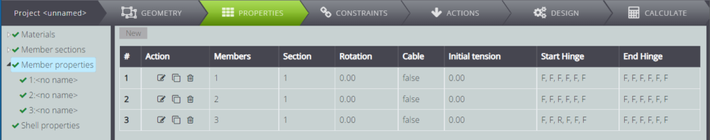
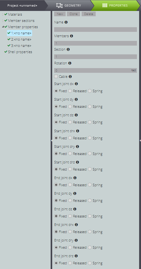
Click on New and give member 1 section 1, as shown below.
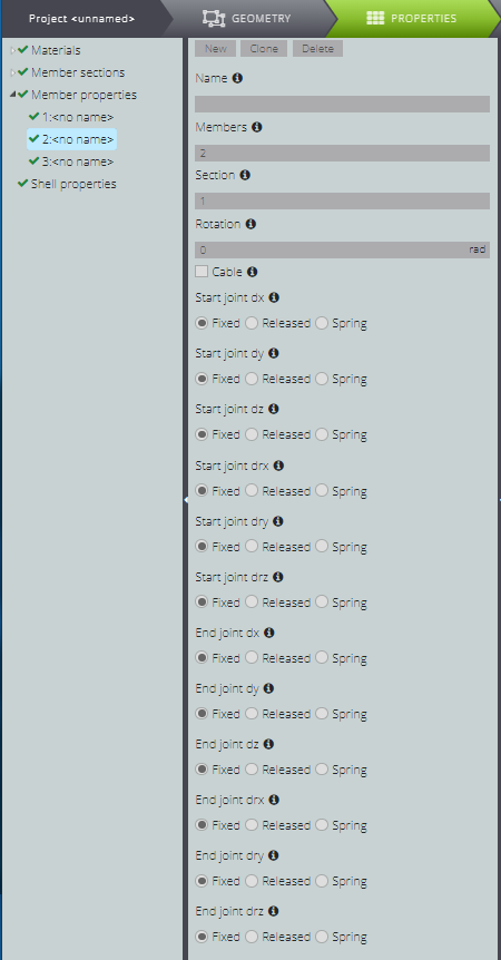
The properties of member 2 do not differ substantially from the previous one.
You can then generate them by pressing Clone on the properties of member 1 and simply changing the number in the Members field.
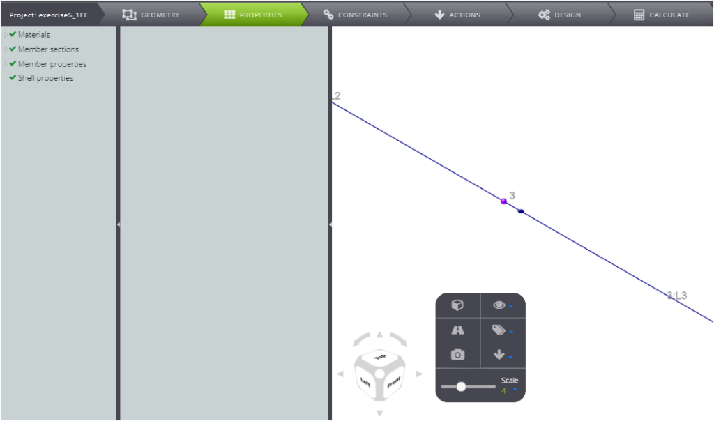
For member 3, free scrolling along z to create the constraint conditions for the vertical release!
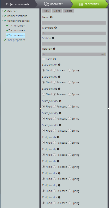
You will see the display of the initial end of member 3 change in the Viewport 3D!
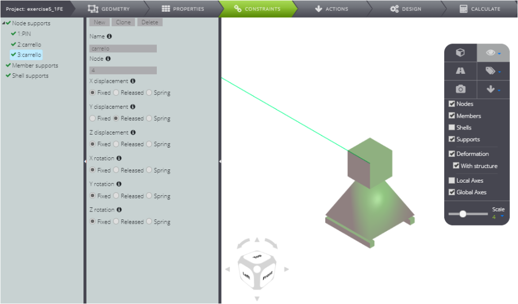
CONSTRAINTS
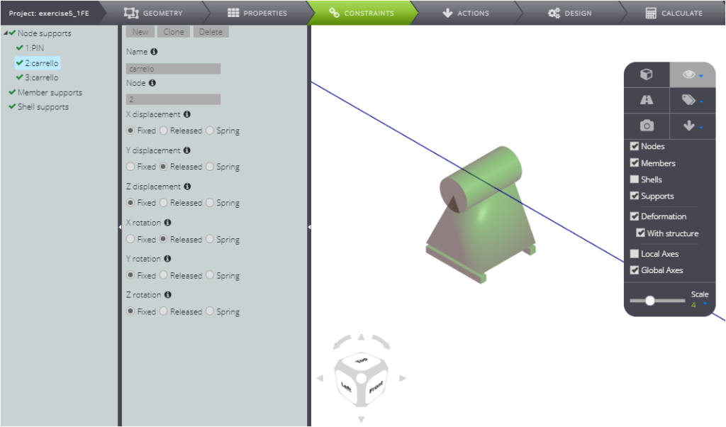
Go to the definition of external constraints on CONSTRAINTS.
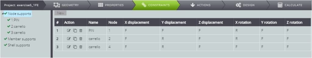
For node 1, leave the rotation around X free.

For node 2, free scrolling along Y and rotation around X.
Finally, for node 3, leave only the scrolling along Y free.
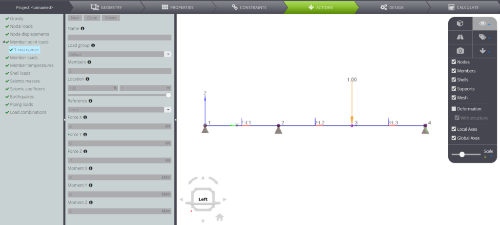
LOADS
Enter the loads on ACTIONS: type -1 in the Force Z field and move it to the end of member 2.
Now that you have correctly defined geometry, properties and boundary conditions, all you have to do is calculate the structure!
ANALYSIS
Click on CALCULATE, then Start calculation.
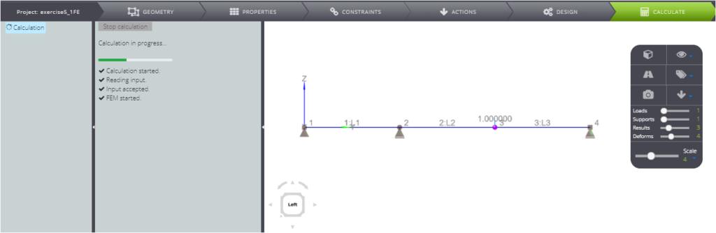
All the results will be available for you in a few seconds: you can consult them by selecting them in the Entity tree and viewing them in the Viewport 3D.
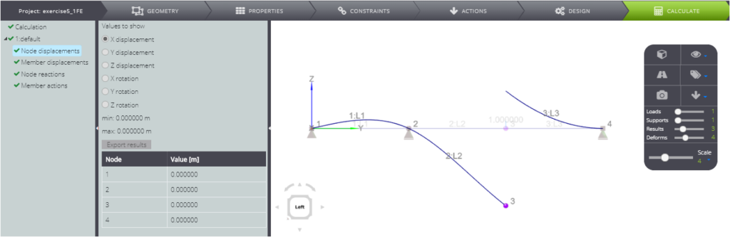
This exercise is also used in our Verification manual: here we compared the results of the analytical solution with the numerical ones.