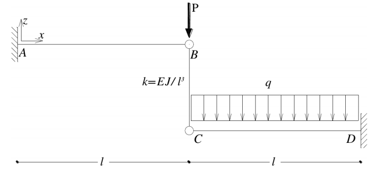
In this page we explain how to model a double cantilever with the ends connected by a truss. You can also find this model among public projects in WeStatiX.
Start by clicking GEOMETRY.
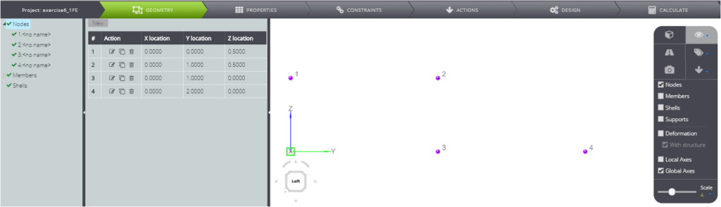
Create nodes with coordinates:
- 1: ( 0 ; 0 ; 0.5 )
- 2: ( 0 ; 1 ; 0.5 )
- 3: ( 0 ; 1 ; 0 )
- 4: ( 0 ; 2 ; 0 )
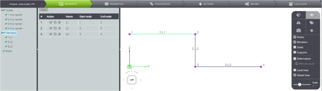
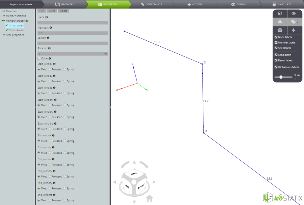
Create members. Progressively connect nodes 1 and 2, then 2 and 3 and finally 3 and 4.
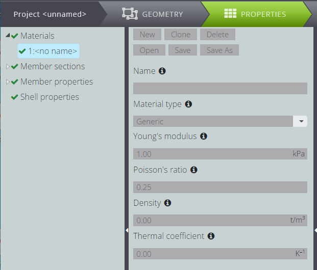
Go to PROPERTIES.
Define the material: fill in the Materials fields as follows.
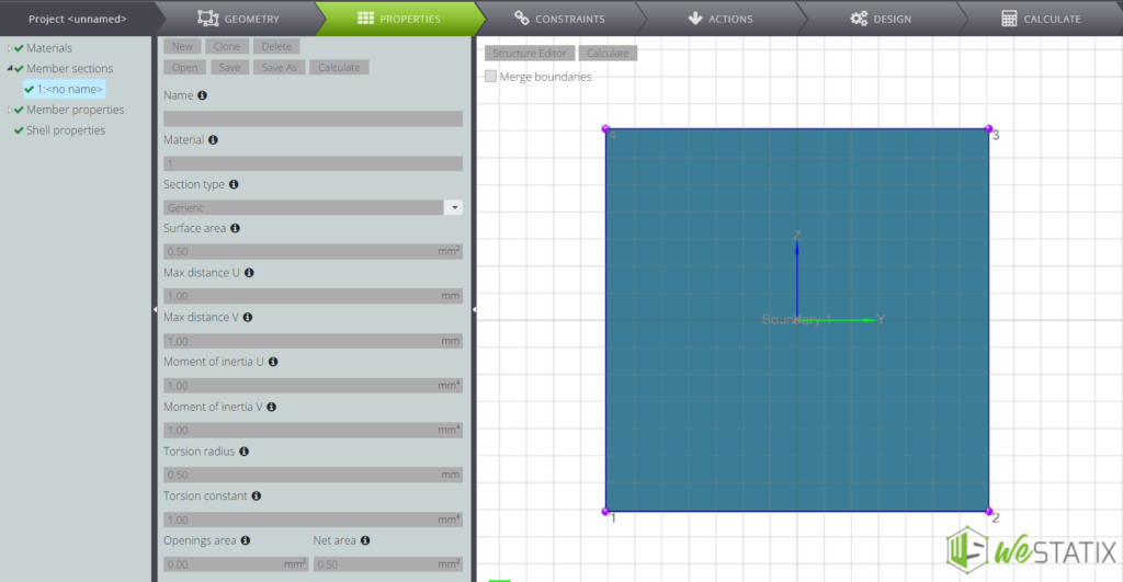
Define also the parametric section.
Now attribute the features to the various members by clicking on Member properties.
Assign section 1 to members 1 and 3 by filling in the fields as follows.
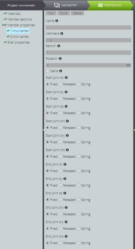
To insert the inner hinges, when you define member 2 releases the dry rotations in the start and end node.
Note that the local reference system of member 2 has been rotated by -90° by filling in the Rotation field.
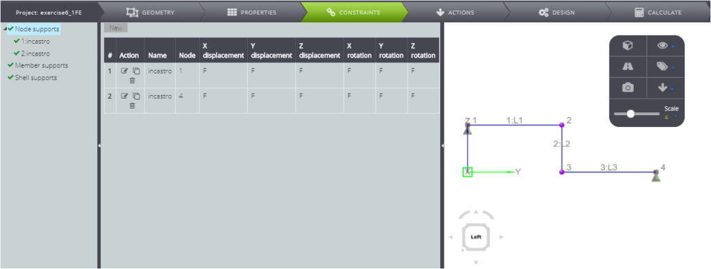
Impose external constraints by clicking on the CONSTRAINTS Tab and then blocking all degrees of freedom of nodes 1 and 4.
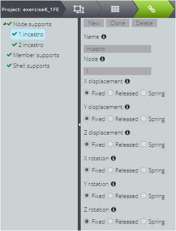
Here we report the summary table for the constraints.
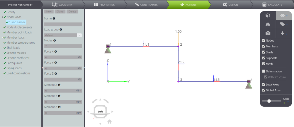
Finally, define the loads. Click ACTIONS.
To insert the concentrated load on node 2, press Nodal loads and then New.
Then fill in the Force Z field with the value -1.
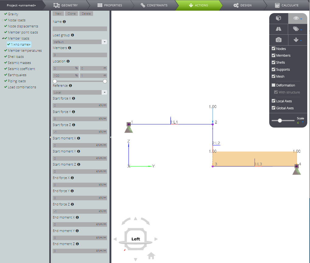
To enter the concentrated load, specify its components on member 3 in Member loads. See how the fields in the figure below are filled in.
Are you finished? Launch the analysis! Press CALCULATE and Start Calculation.
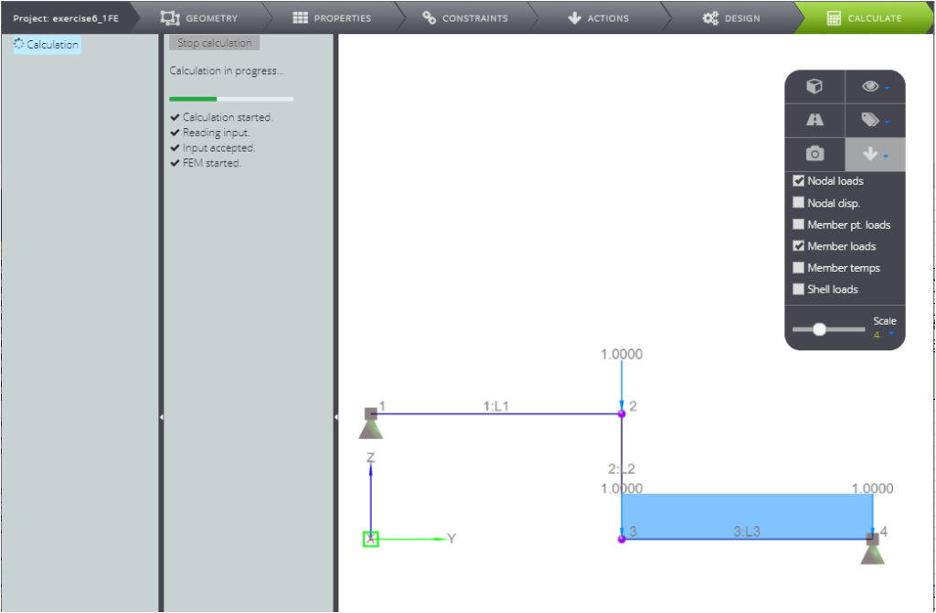
All results will be available for you in seconds.
For this example we discussed them in our Verification manual, comparing them with the analytical solution. Check it out!
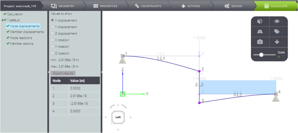
If you are interested, you can find the results commented in our Validation Manual.