In this section we explain you how to quickly model an industrial flooring subject to the load of a truck. The model is available for you in WeStatiX.
We will also show you how the results vary using fiber-reinforced concrete! For this you can see a second model where we have changed the material properties.
This tutorial loads the type of reinforcement steel from the WeStatiX database. If your current plan does not allow the use of the Database, you can upgrade at any time, or define the reinforcement steel parametrically.
Step by Step
GeometrY
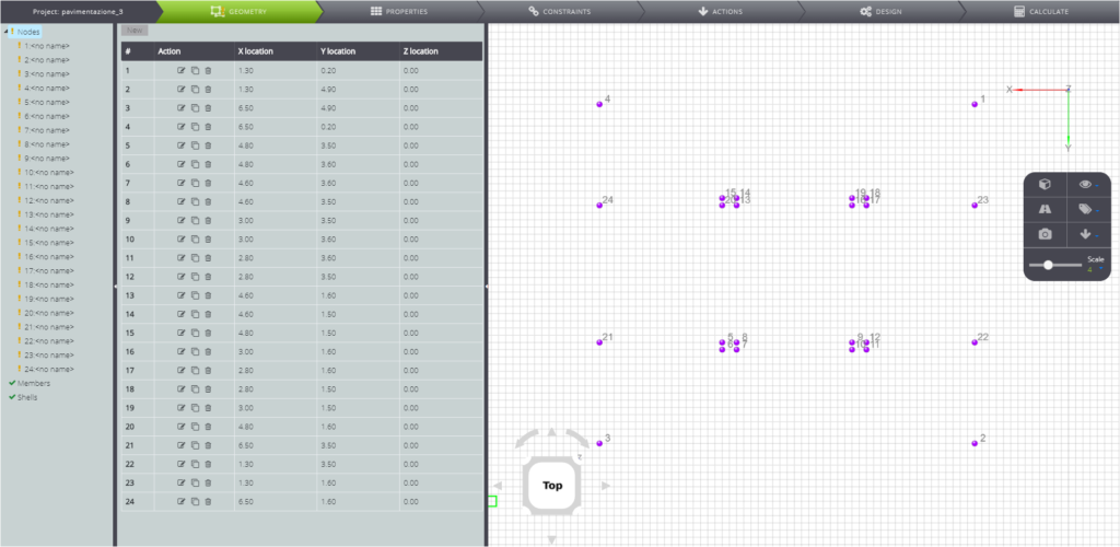
Let’s start by creating the geometry: click on GEOMETRY on the Tab Bar.
Create the nodes with the coordinates of the table below.
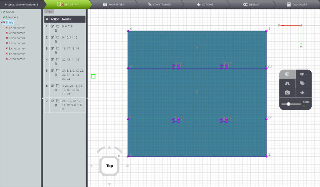
You have finished creating the geometry! Here is your flooring.
PropERTIES
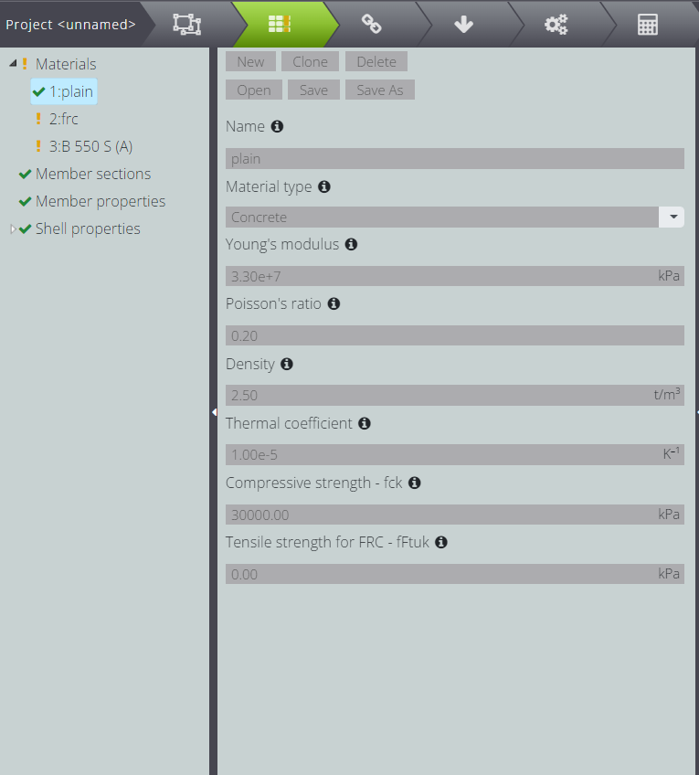
Start defining properties in the PROPERTIES section.
First, create the concrete material as shown below.
Create fiber-reinforced concrete second: Fill in the Tensile strength field with the tensile strength of the material… we’ll see at the end how the results vary!

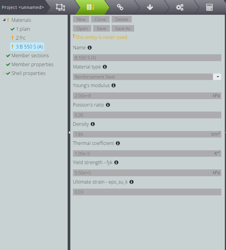
In order to carry out the design of the reinforced concrete section you have to define the properties of the reinforcing steel. Look for it in WeStatiX libraries in Database!
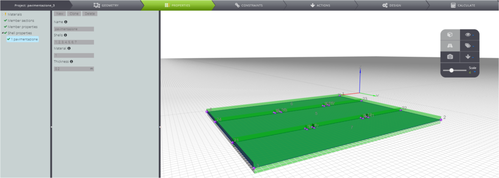
Now attribute the properties to the plate.
- The thickness is constant for all elements and is 0.3m.
- For the first analysis, attribute material 1
- For the second analysis, enter material 2.
CONSTRAINTS
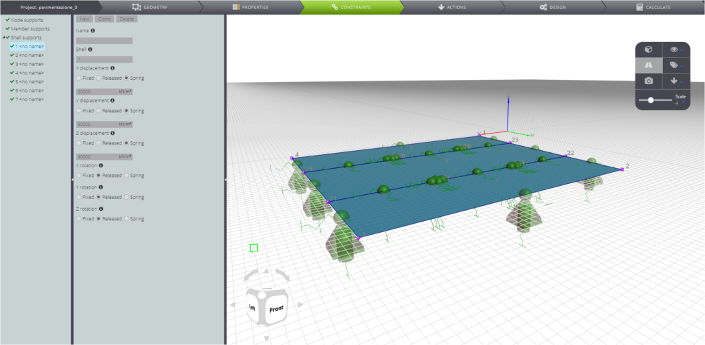
In CONSTRAINTS simulate the Winkler’s elastic floor by inserting a shell support with a stiffness of 90000 kN/m2.
LOADS
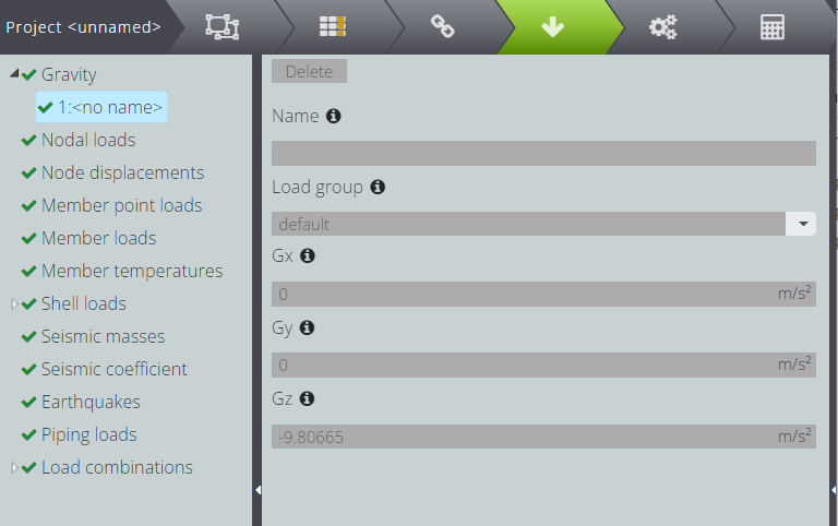
Move to ACTIONS to define model actions. Enter the gravity load specifying the size and direction of the vector in Gz.
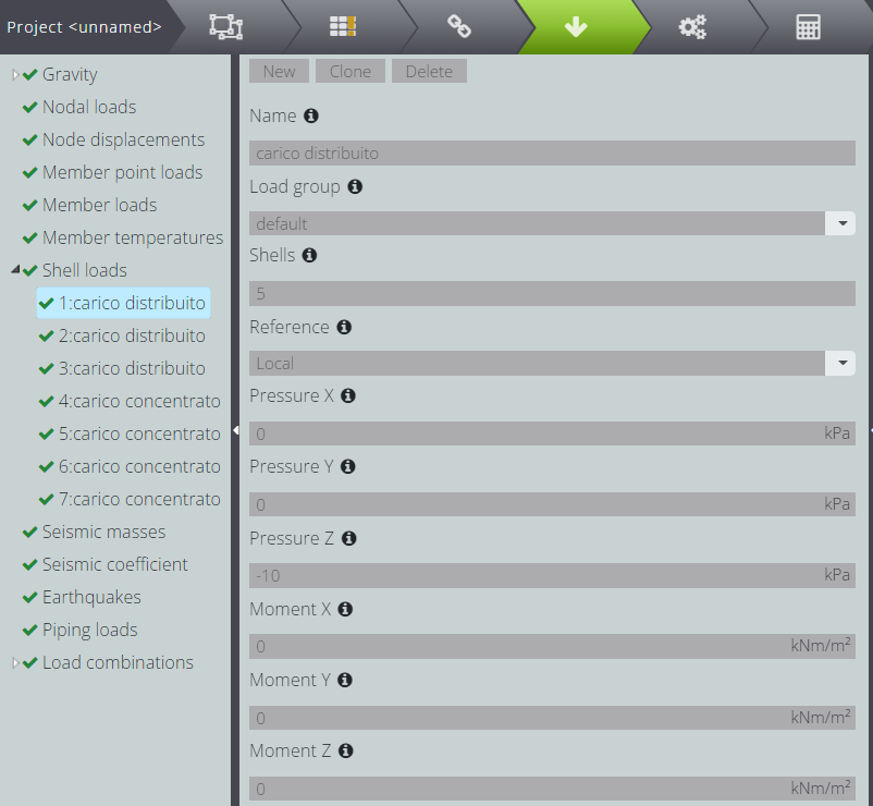
Enter a load of -10kPa in Z direction on shells 5, 6 and 7 .
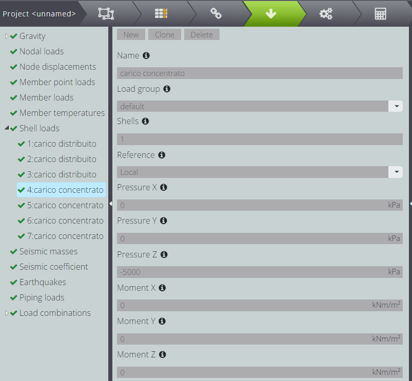
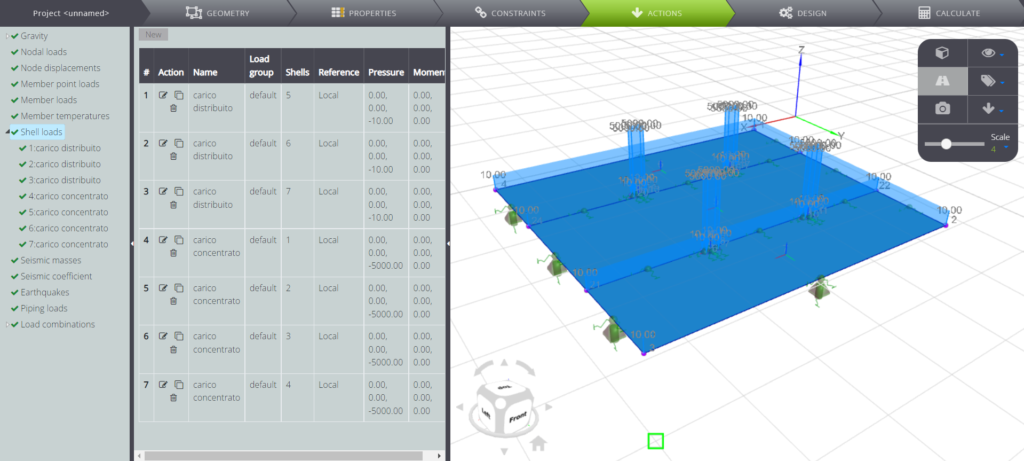
On shell 1, 2, 3 and 4 instead insert a pressure of -5000kPa, representative of the truck stopped on the plate.
This is what your loads look like in Viewport 3D.
To proceed with the design of the reinforced concrete elements, at least one load combination must be defined.
To do so, press on Load combinations and then on New.
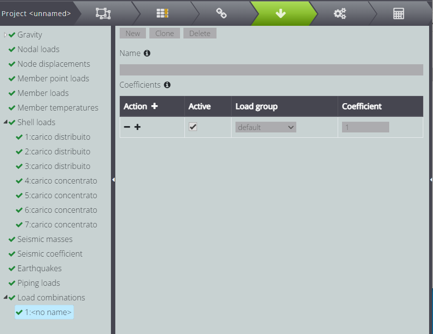
Then simply tap on Action to add a Load group. In our case the only Load group present is default and we don’t need to specify a different coefficient from one. At this point you can enter a name as you like and then proceed with the next step!
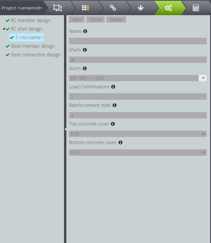
REINFORCED CONCRETE SECTION DESIGN PARAMETERS
Now move to DESIGN and specify the design parameters as follows.
Go to CALCULATE and launch the analysis!
RESULTS
In the Entity tree, under RC shell design, you can find the designing results.
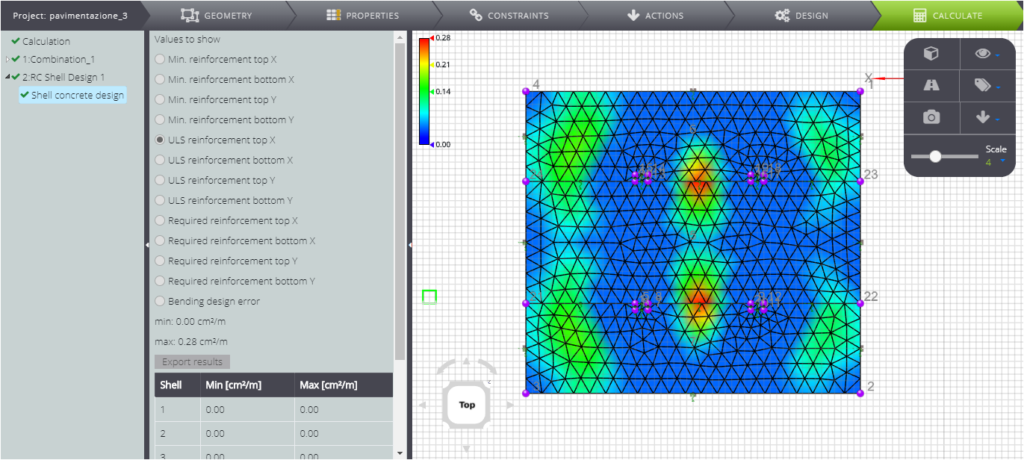
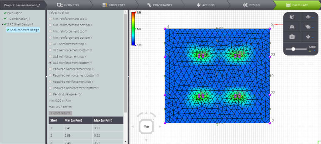
Here we see the results for the project at the Last Limit State.
This is what the contour for the upper reinforcement design in X direction looks like.
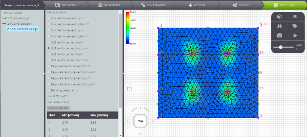
…and this is the lower reinforcement design in the same direction.
Similarly, you can see the reinforcement needed to verify the SLU checks in the Y direction, for the top.
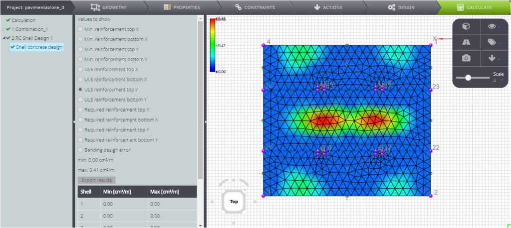
And finally, the reinforcement to be placed at the bottom in the Y direction.
Now observe the results you get by assigning the properties of fiber-reinforced concrete to the plate, with the same geometry and boundary conditions.
All contours for the project reinforcement at the SLU have uniform zero value.
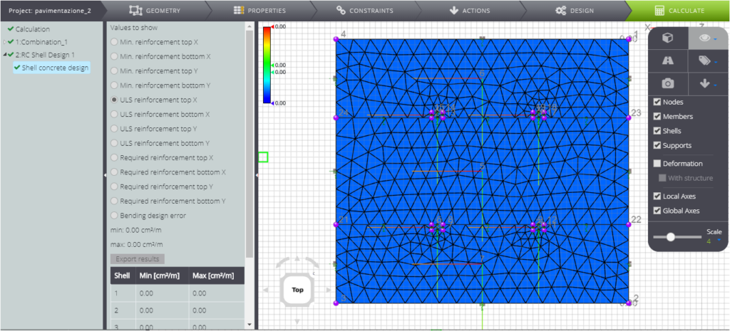
This is due to the intrinsic tensile strength of fiber-reinforced concrete, which therefore does not require reinforcement to meet the strength tests!