In this tutorial we explain how to model and analyze a reinforced concrete frame. We have also performed the design of reinforced concrete elements, so in the results you will also find the calculation of the reinforcement according to standards.
The model is available in the WeStatiX library.
If the template contains too many members for your WeStatiX plan, you can easily change it or use the tips below to define a less complex structure.
GEOMETRY
Start by clicking on GEOMETRY and create all the nodes. Remember that once you have created the foreground, it will be easy to duplicate the nodes with Clone, and then only change the z coordinate.
Then create members.
PROPERTIES
Switch to PROPERTIES.
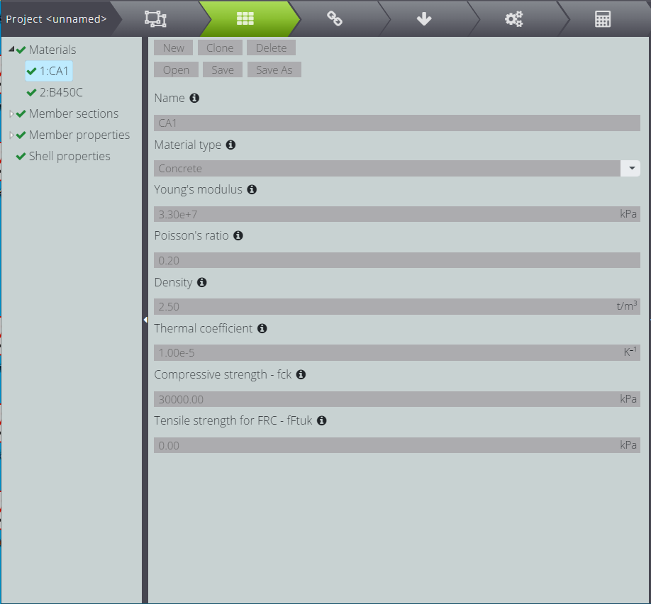
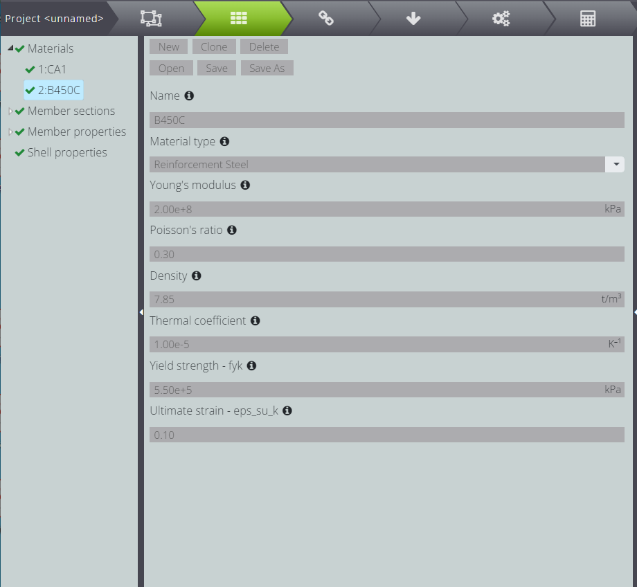
Define the concrete for your structure. Choose it from the Database libraries, then move to Parametric to save the settings.
To carry out the design of the reinforced concrete section, it will be useful to define the properties of the reinforcing steel! Add a new material and remember that in Material type there must be Reinforcement Steel.
Now assign sections and materials to individual elements.
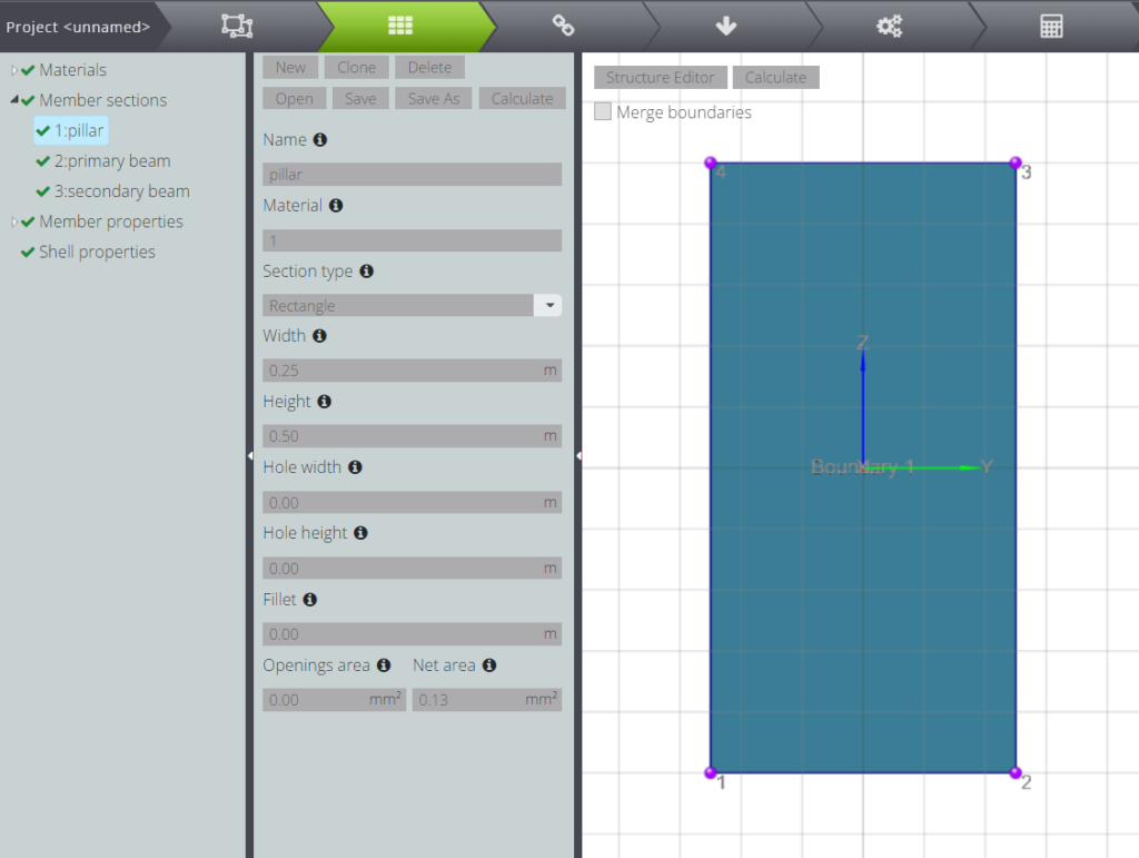
To define the abutment section, click on Member sections and then on New.
At this point you can fill in the Name field so that you can more easily distinguish the section you are creating.
Assign the material of the current section by entering the corresponding index in the Material field.
In the current project the pillars must have a rectangular section 25 x 50 cm: to create it, select Parametric and then fill in the Width and Height fields: remember that the lengths must be specified in meters!
Note that in the material field you will only have to enter concrete, while steel for reinforcement will only have to be specified when you set the parameters for the concrete section design.
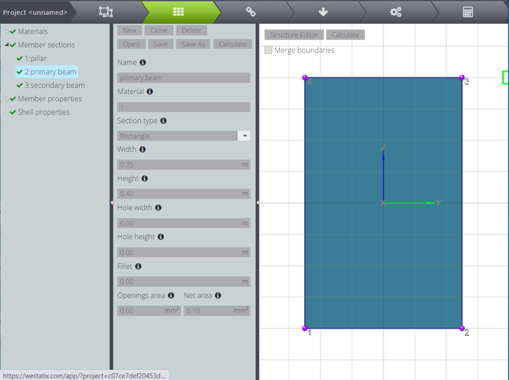
You can repeat the same process to create the sections for the primary beams…
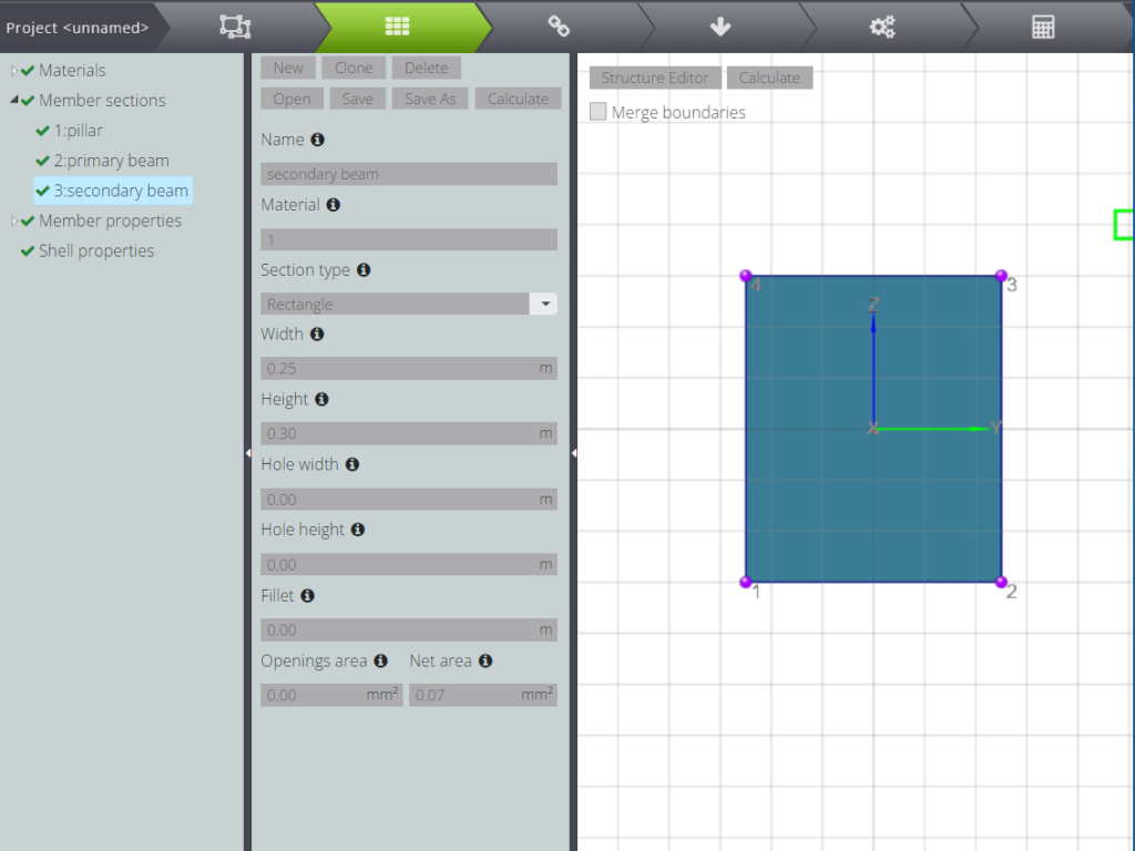
…and for the secondary beams!
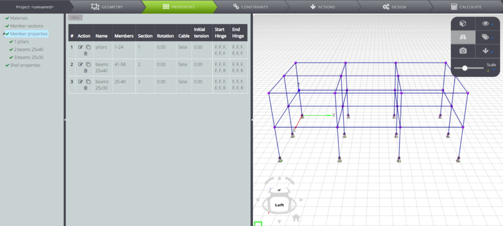
At this point you can create three Member properties by assigning material and section to the various members of the structure. In the table below you can then see three different groups: main beams, secondary beams and pillars.
Now that you have finished describing the geometry of the problem, switch to boundary conditions.
CONSTRAINTS
Under CONSTRAINTS you can define the constraints.
Fix all the nodes at the base.
LOADS
Define the loads on ACTIONS. In this model, each element has been assigned a distributed load representative of structural permanent loads, carried permanent loads and accidental loads.
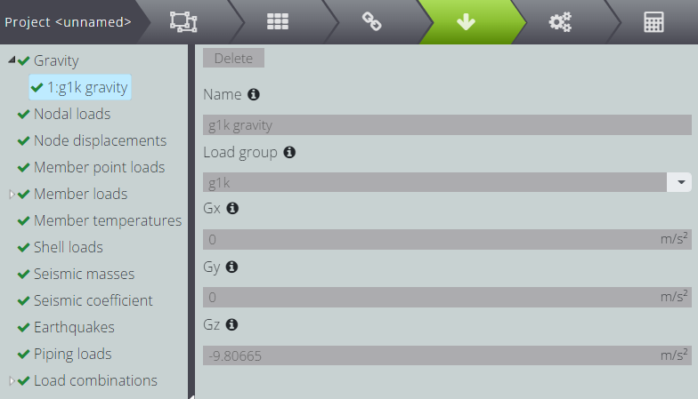
To distinguish them and then insert them in load combinations, insert labels in Load group
- g1k : structural permanent loads
- g2k : carried permanent loads
- qk : accidental loads
- qsnow : snow loads
As you see below, for example, the gravity load has been assigned to the group of structural permanent loads.
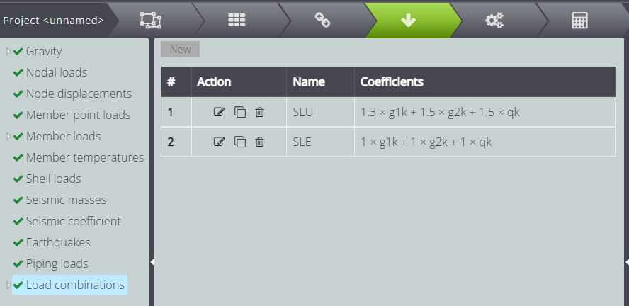
Now you can create load combinations! In Load combinations you find the labels you defined before and you can specify the coefficient to be applied to the characteristic loads to transform them into design loads.
PROJECT OF REINFORCED CONCRETE SECTIONS
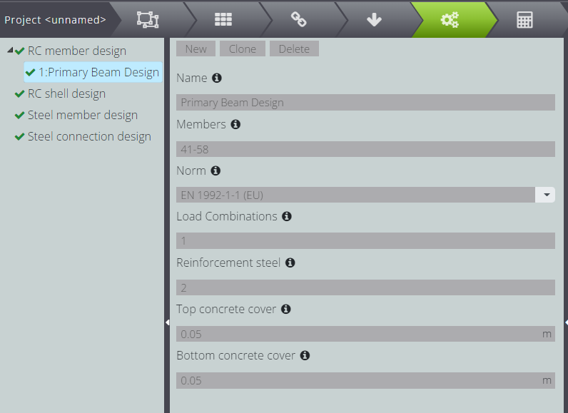
At last, to execute the concrete section design, switch to DESIGN and press RC member design.
Click on New and fill in the fields as below: in this tutorial the section design of all the main beams is executed.
ANALYSIS & RESULTS
Once you have finished describing the geometry, properties and boundary conditions, go to CALCULATE and start the analysis by pressing Start calculation.
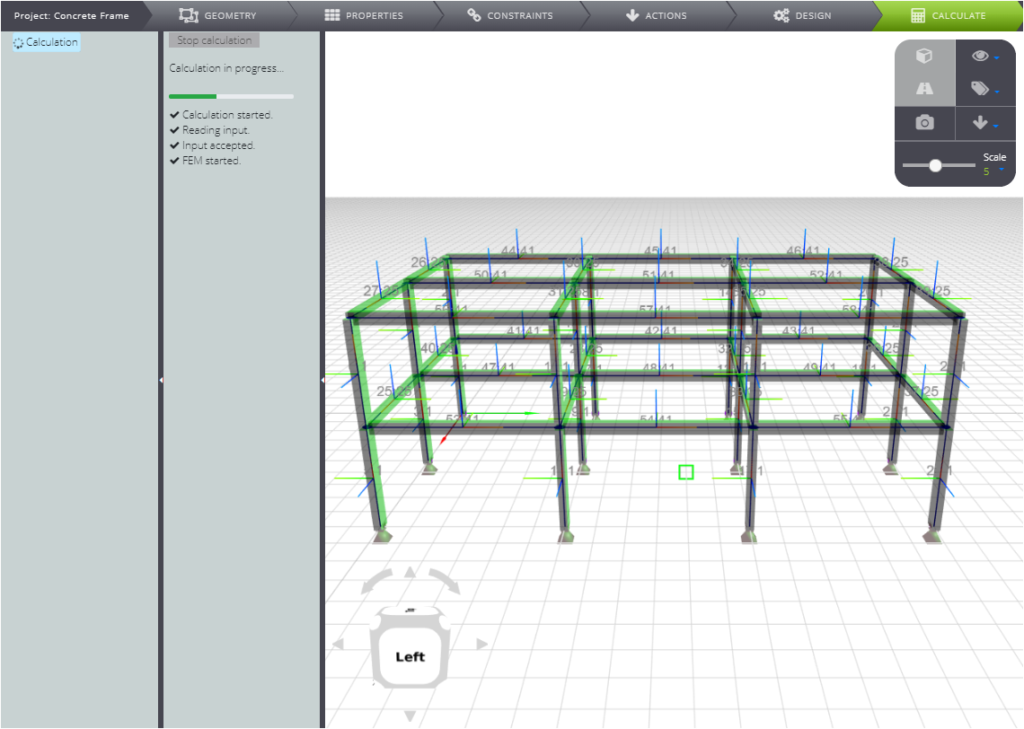
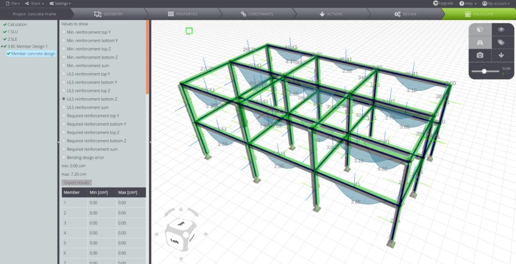
In the Entity tree you will find the results divided between the load combinations you defined previously.
You will also find the results of the reinforced concrete sections project!