With this tutorial we show you how to model a circular plate of radius a and thickness h clamped at the edges and subject to uniform load q. If you want to load this model and see all the details, you can always find it in WestatiX public projects.
Launching the simulation of this tutorial requires some features that may not be available in the WeStatiX Free plan. You can still change plan at any time.
The problem data is listed below:
Radius \( a = 10 m \) ;
Thickness \( h = 1 m \) ;
Young’s modulus \( E = 10^8 kPa \) ;
Poisson’s ratio \( \nu= 0.3 \) ;
Pressure \( q = -10 kPa \).
Geometry
Start by creating the nodes! Then press on the GEOMETRY Tab and select Node in the Entity Tree.
We create one in the center of the plate and then others on the edge of the plate, following the law:
\( x_i = a sen \theta_i ;\\ y_i = a cos \theta_i \)Where \( \theta_i = \theta_{i-1} + \Delta \theta \).
For this example we have chosen an interval with \( \Delta \theta = 15° \)
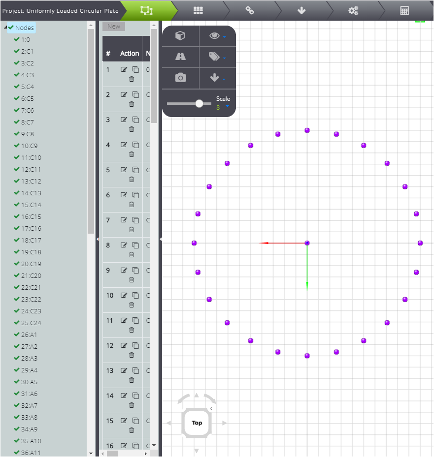
In the table below you can read the coordinates of the nodes
| N | X | Y | Z |
|---|---|---|---|
| 1 | 0.00 | 0.00 | 0.00 |
| 2 | 0.00 | 10.00 | 0.00 |
| 3 | 2.59 | 9.66 | 0.00 |
| 4 | 5.00 | 8.66 | 0.00 |
| 5 | 7.07 | 7.07 | 0.00 |
| 6 | 8.66 | 5.00 | 0.00 |
| 7 | 9.66 | 2.59 | 0.00 |
| 8 | 10.00 | 0.00 | 0.00 |
| 9 | 9.66 | -2.59 | 0.00 |
| 10 | 8.66 | -5.00 | 0.00 |
| 11 | 7.07 | -7.07 | 0.00 |
| 12 | 5.00 | -8.66 | 0.00 |
| 13 | 2.59 | -9.66 | 0.00 |
| 14 | 0.00 | -10.00 | 0.00 |
| 15 | -2.59 | -9.66 | 0.00 |
| 16 | -5.00 | -8.66 | 0.00 |
| 17 | -7.07 | -7.07 | 0.00 |
| 18 | -8.66 | -5.00 | 0.00 |
| 19 | -9.66 | -2.59 | 0.00 |
| 20 | -10.00 | 0.00 | 0.00 |
| 21 | -9.66 | 2.59 | 0.00 |
| 22 | -8.66 | 5.00 | 0.00 |
| 23 | -7.07 | 7.07 | 0.00 |
| 24 | -5.00 | 8.66 | 0.00 |
| 25 | -2.59 | 9.66 | 0.00 |
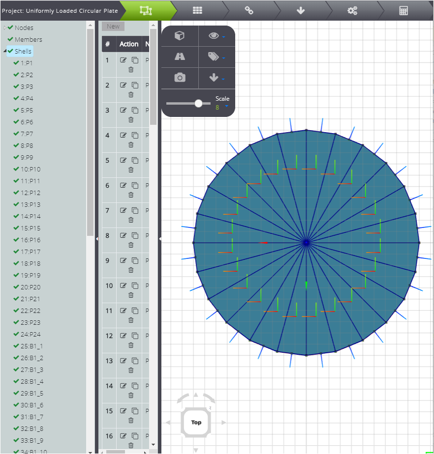
By joining the nodes in the graphical interface you can define all the Shells that make up the plate.
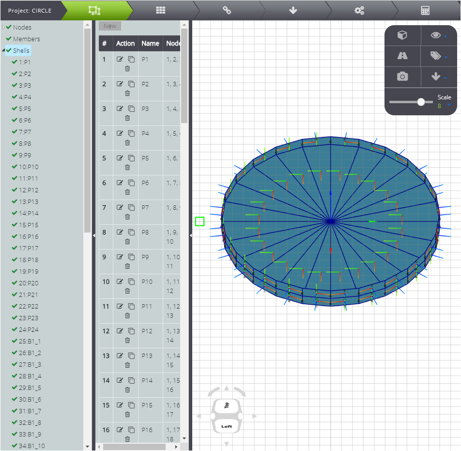
Now create the trapped edge: use Clone on nodes 2 to 25 and change the z coordinate to +1. In the same way, create another row with -1 coordinate.
Now create shells: you can move around the graphical interface and merge nodes.
In this way you have defined the geometry of the problem. After that you can go to the properties.
Properties
Click on PROPERTIES on the Tab Bar.
Define immediately the characteristics of the material on Materials.
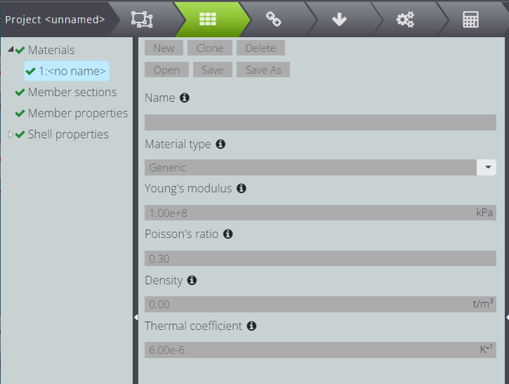
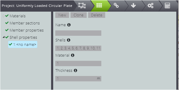
Finally, attribute the material and thickness to all the plates: fill in the fields as shown in the image below.
Constraints
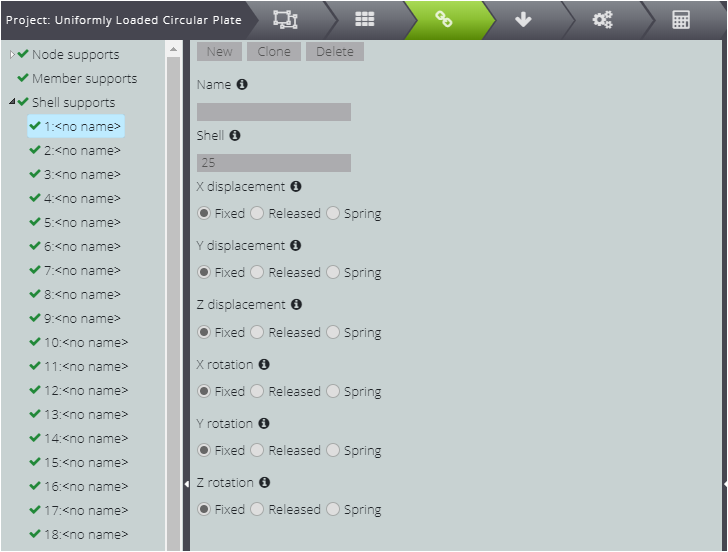
To fit the edges of the plate blocks all movement and rotation of the shells that make up the edge.
Open the CONSTRAINTS Tab Go to Shell supports in the Entity tree and select Fixed for all degrees of freedom. After that, using Clone you only need to change the Shell field to create a constraint with the same properties for the other elements.
At last, to block the system in space, block one of the nodes: to do so, press Node supports in the Entity tree!
Loads
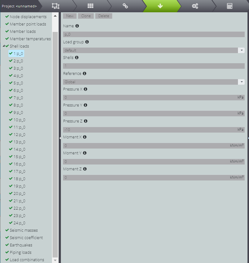
Now move to ACTIONS and press on Shell actions, so you can enter the distributed load.
For each Shell making up the plate, fill in the Pressure Z field by writing -10kPa.
You have defined all the features of the system! Go to CALCULATE to launch the analysis and read the results.
For this example there is an analytical solution, with which we compared the results of WeStatiX in our Verification Manual.