In this example we use WeStatiX to design a RC cross-section with symmetrical reinforcement and we verify the results. We consider the cantilever beam represented in the following figure.
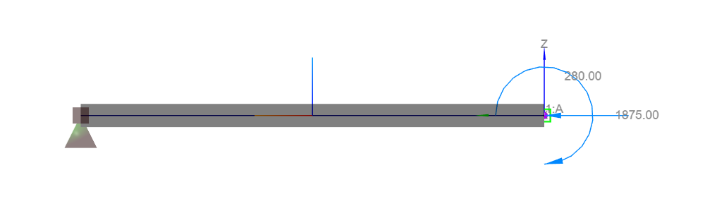
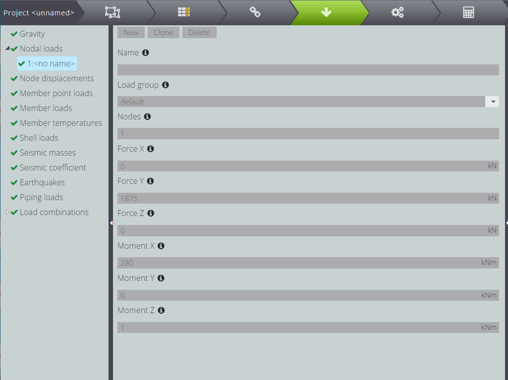
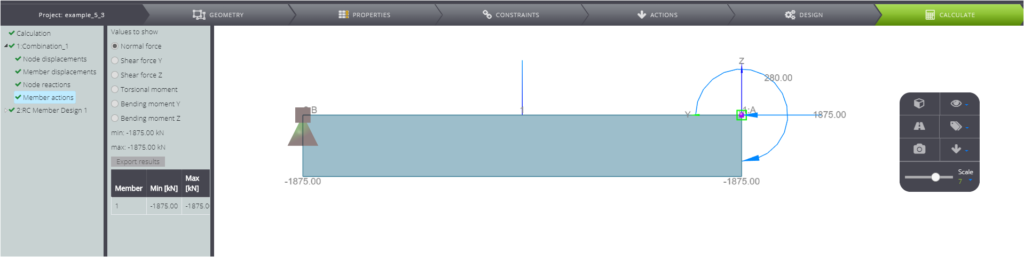
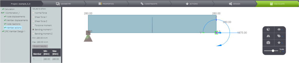
You can find the beam model in WestatiX ready for the calculation, while the loading conditions are summarized in the following table.
| Bending moment | \(M_{Ed}\) | \(\) | 280 | kNm |
| Axial force | \(N_{Ed}\) | \(\) | 1875 | kN |
| Eccentricity | \(e_{tot}\) | \(\) | 0,15 | m |
The cross section characteristics are listed in the table below
| Description | Symbol | Value | UM | |
|---|---|---|---|---|
| Overall width of a cross-section | \(b\) | \(\) | 300 | mm |
| Height | \(h\) | \(\) | 500 | mm |
| concrete cover | \(d_1\) | \(\) | 50 | mm |
| ratio for interaction diagram choice | \(d_1/h\) | \(\) | 0,10 | – |
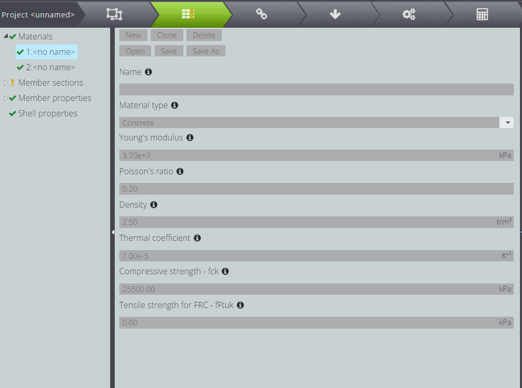
And finally, here are the material parameters.
| Description | Symbol | value | UM | |
|---|---|---|---|---|
| Characteristic compressive cylinder strength of concrete at 28 days | \(f_{ck}\) | \(\) | 25.500,00 | kPa |
| Characteristic yield strength of reinforcement | \(f_{yk}\) | \(\) | 500.000,00 | kPa |
| Coefficient taking account of long term effects | \(\alpha_{cc}\) | \(\) | 1,00 | – |
| Partial factor for concrete | \(\gamma_c\) | \(\) | 1,50 | – |
| Partial factor for reinforcing steel | \(\gamma_s\) | \(\) | 1,15 | – |
| Design value of concrete compressive strength | \(f_{cd}\) | \(\alpha_{cc} f_{ck}/\gamma_c\) | 17.000,00 | kPa |
| Design value for yield strength of reinforcement | \(f_{yd}\) | \(f_{yk}/\gamma_{s}\) | 434.782,61 | kPa |
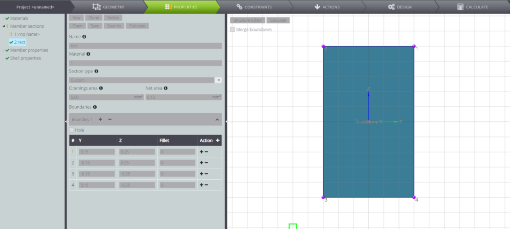
In the following pictures you can see how the section and material parameters have been selected in WeStatiX.

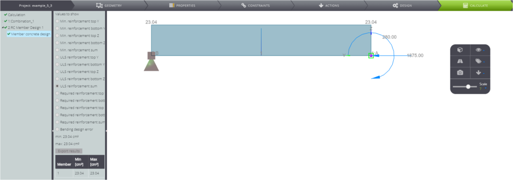
Once you created the model as shown above, you can start the calculation. You will obtain the results shown in the following pictures.
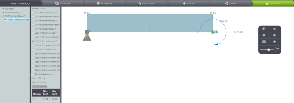
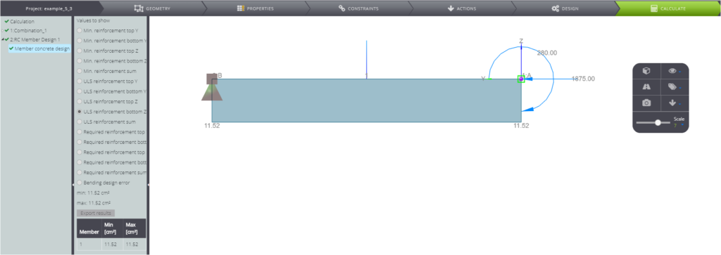
The computed reinforcement is symmetric and the total cross section reinforcement area is equal to \( A_{s,tot}=23,04 cm^2 \).
We can verify the results using the interaction diagrams for symmetric reinforcement.[1]
The first step consists in the calculation of the following parameters
| Parameterized axial force | \(\nu\) | \(N_d/b \cdot h \cdot f_{cd}\) | 0,74 | |
| Parameterized bending moment | \(\mu\) | \(M_d/b\cdot h^2 \cdot f_{cd}\) | 0,22 |
Then, we can choose the interaction diagram to design a RC section with symmetrical reinforcement and reach the ratio \( \frac{A_s f_{yd}}{bhf_{cd}}\) as follows.
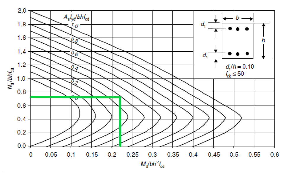
Finally, knowing the ratio you can calculate the total reinforcement area as
| Coefficient from interaction diagram | \( \frac{ A_s \cdot f_{yd} }{ b \cdot h \cdot f_{cd}} \) | 0,40 | – | |
| Total reinforcement area | \(A_{s,tot}\) | \(\) | 23,45 | cm^2 |
So you can compare the two solutions as
Therefore, we can conclude that the design solution calculated by WeStatiX is verified.
[1] A.W.. BEEBY and R.S: NARAYANAN – Designers’ guide to Eurocode 2: design of concrete structures. – Designers’ guide to EN1992-1-1 and EN1992-1-2 Eurocode 2: design of concrete structures. General rules and rules for buildings and structural fire design.