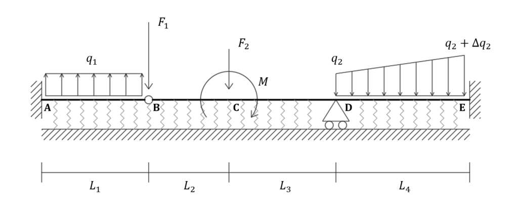
In this tutorial you can learn how to model the system shown in the figure below. It is an elastic beam resting on a Winkler springs foundation. You can find the model here or create it by yourself just following the procedure herein described!
You can find this and other examples also in WeStatiX.
Geometry
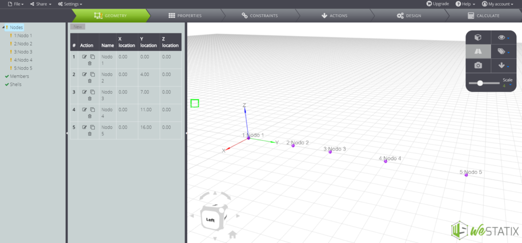
In the Tab Bar clic on GEOMETRY to start creating the nodes.
Nodal coordinates are the following:
- A: (0; 0; 0)
- B: (0; 4; 0)
- C: (0; 7; 0)
- D: (0; 11; 0)
- E: (0; 16; 0)
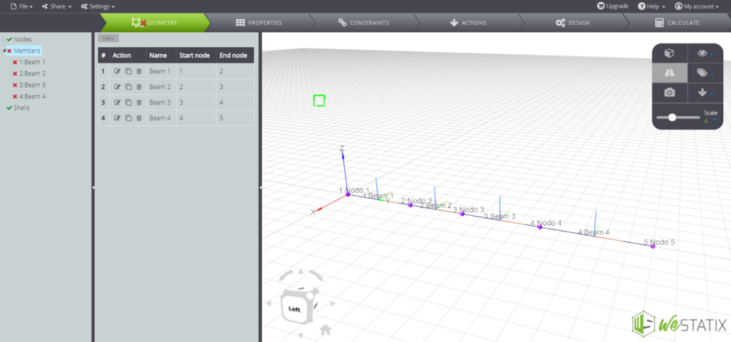
Go on and create beam elements, using the Members command:
Material and section properties
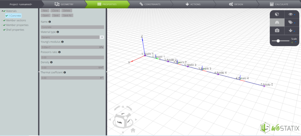
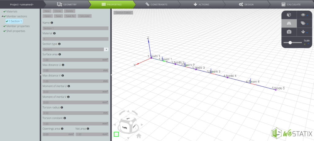
Now you can define the properties of the elements! Continue to the Tab Bar and enter the PROPERTIES command. Here you can define the material characteristics:
In the left menu you can now define the characteristics of the beam cross-section:
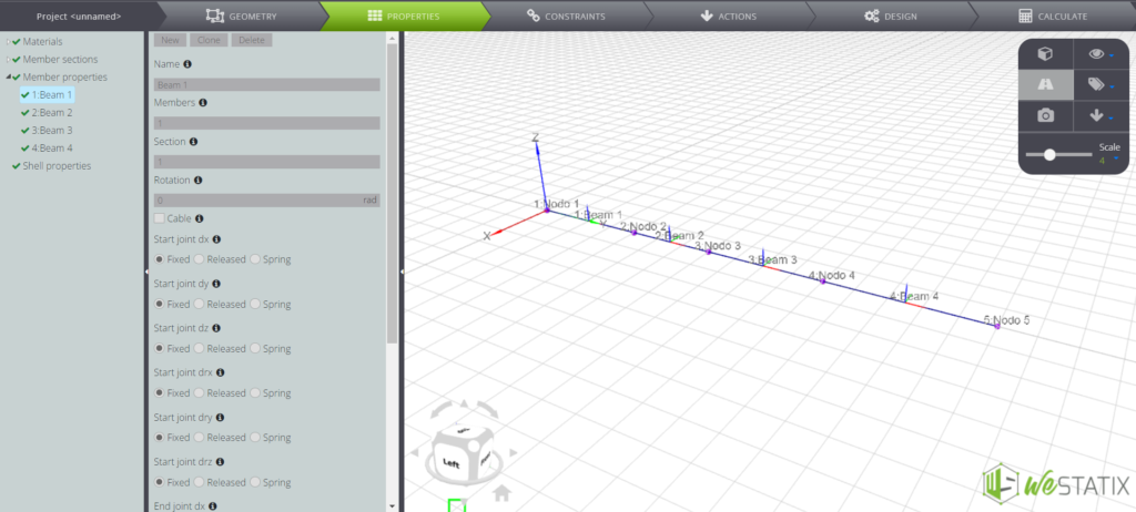
Now, just assign the cross-section properties to each beam element:
Constraints
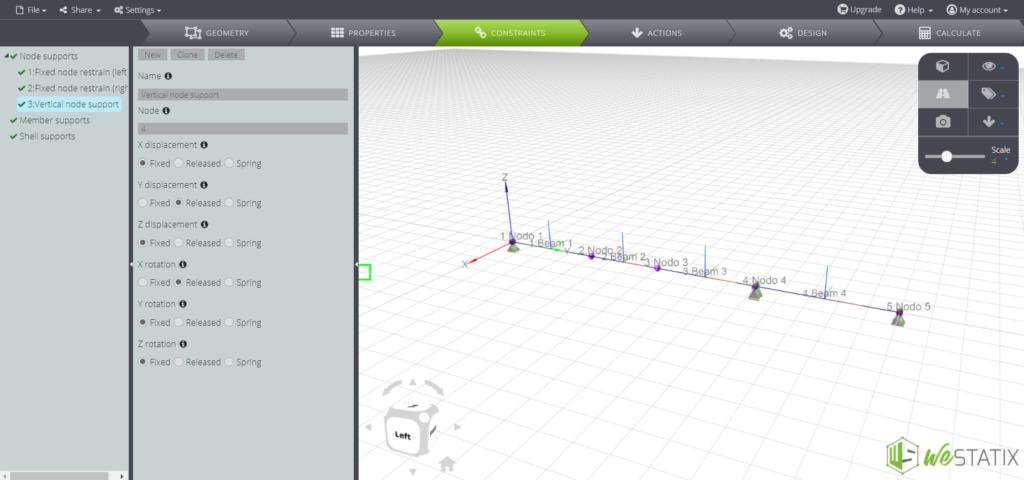
Follow the Tab Bar and enter the CONSTRAINTS section. Here you can assign nodal restraints:
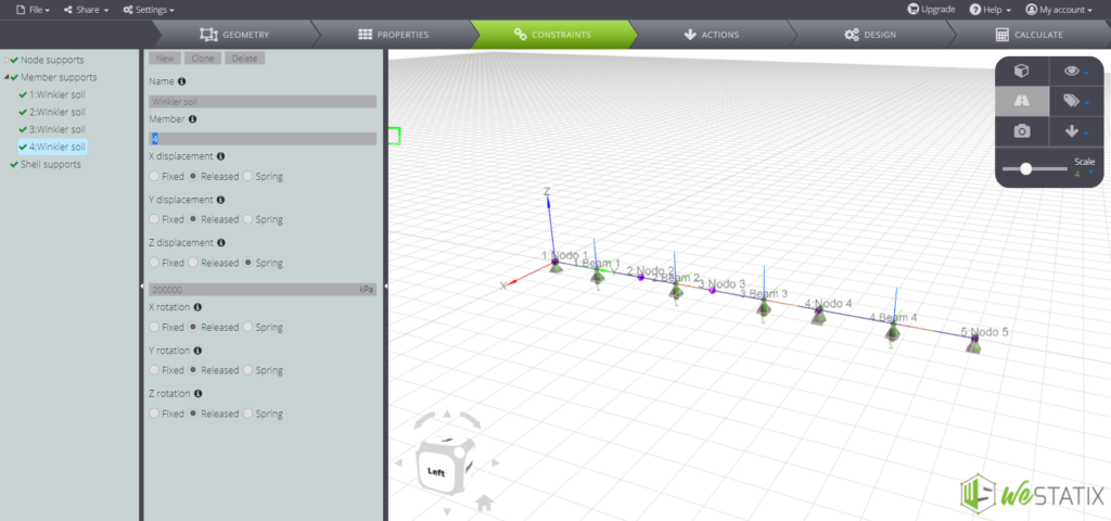
Now it’s time to assign the vertical support restraints to the beam elements. The Winkler foundation consists of a bed of independent elastic springs supporting the beam. Use the Member supports command:
Loads
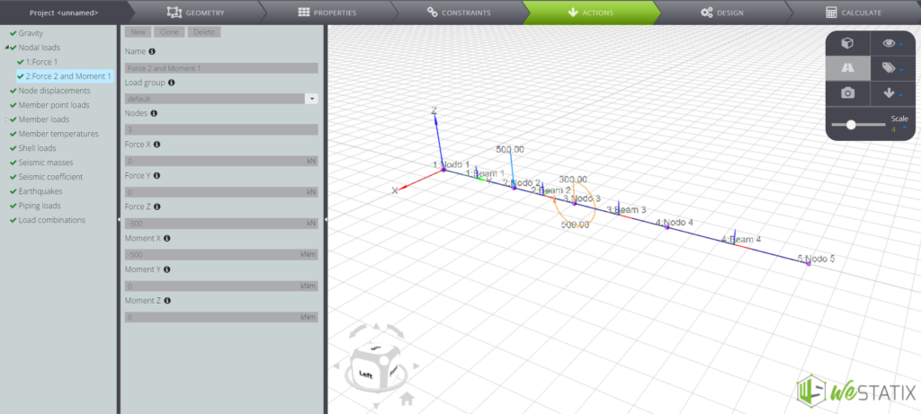
It is now time to assign the loads to the model, entering the ACTIONS command! You can first enter the Nodal loads:
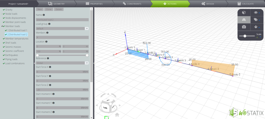
In the same menu you can also find the Member loads command, which allows you to apply both constant and variable distributed loads along the beams:
Results
Here we are! The model is ready and you can proceed to the Tab Bar in the CALCULATE section, where you can launch the solution by clicking on the “Start calculation” button. When solution process have finished, you can display different types of results, by navigating the Entity tree under the default button.
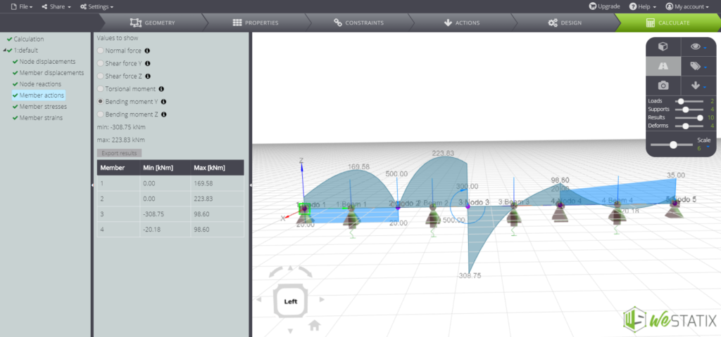
As an example, the bending moment diagram:
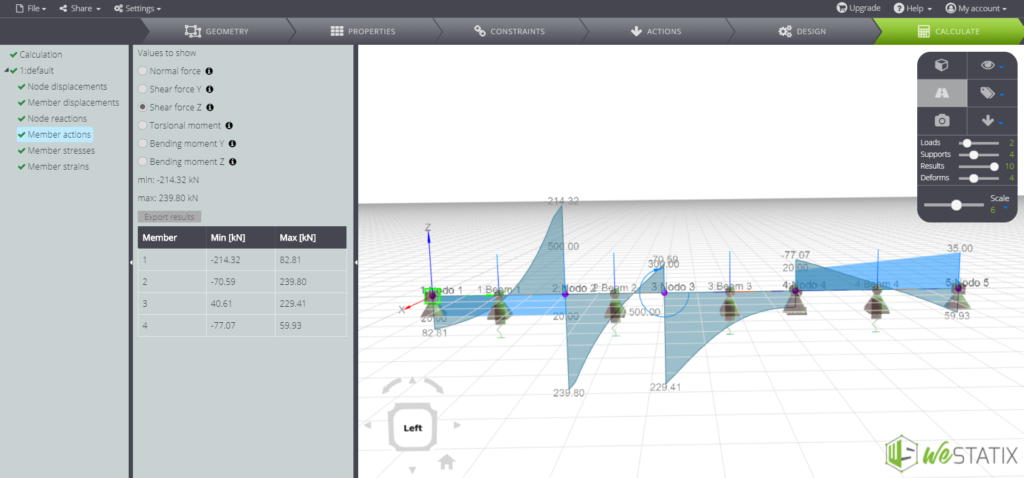
The shear force diagram:
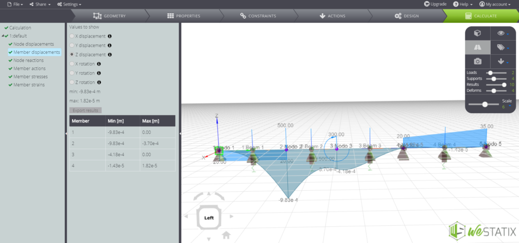
Vertical displacement distribution:
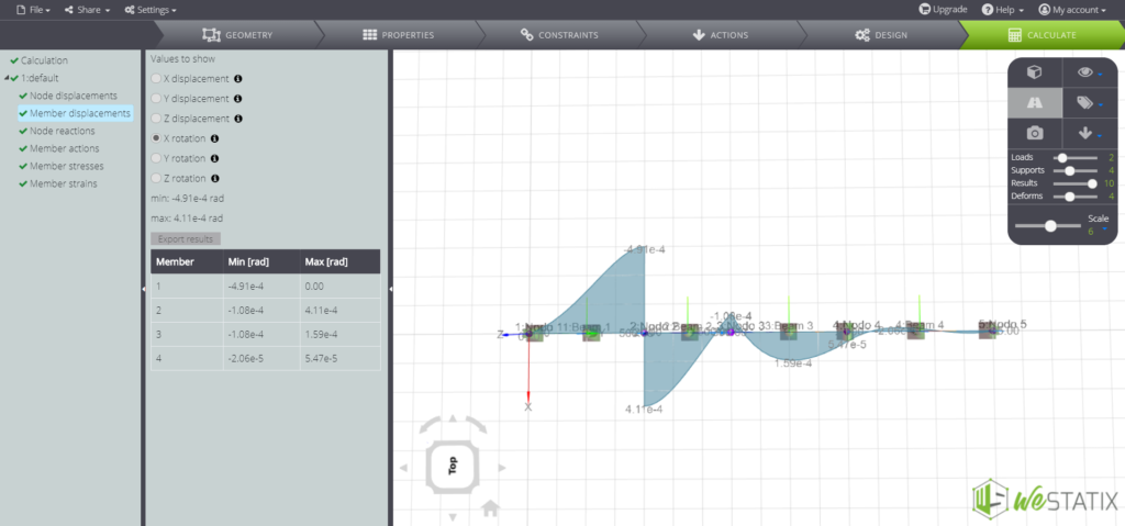
Rotations around cross – section horizontal axis:
Furthermore, in our validation manual you will find a comparison between the numerical and analytical solution for this example!