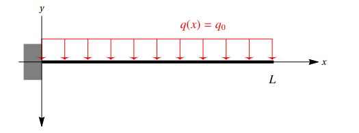
In this page we show you how to model and calculate a cantilever beam with constant load. You can also find it among our tutorials in WeStatiX.
Geometry
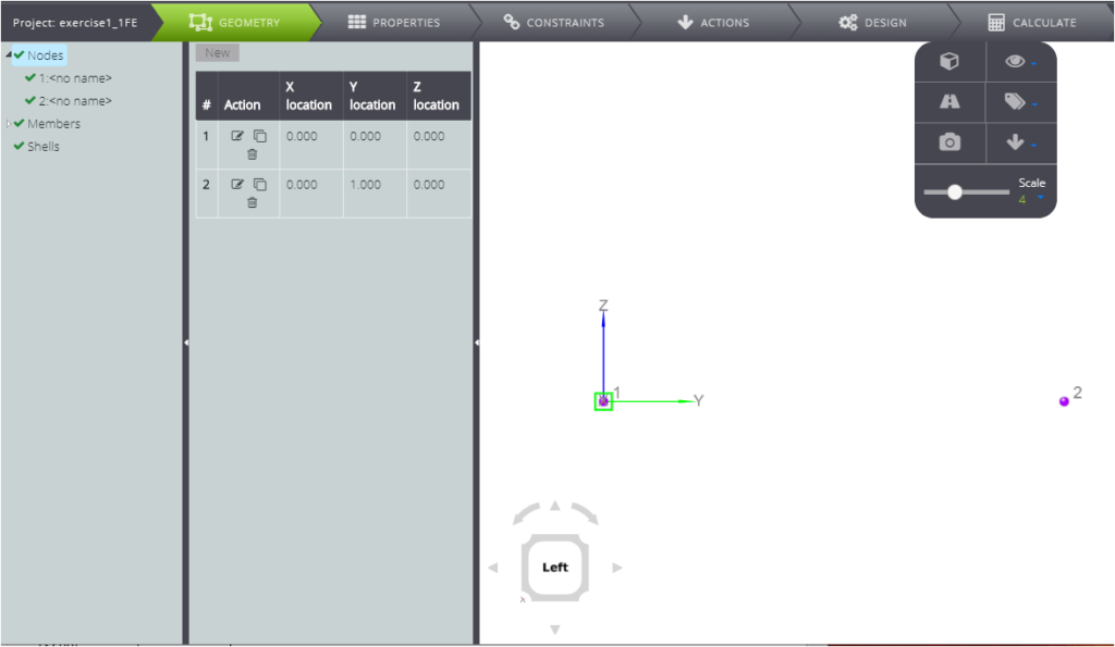
First of all, we create the nodes. The coordinates are:
- 1: ( 0 ; 0 ; 0 )
- 2: ( 0 ; 1 ; 0 )
Go to the Entity Tree
- click on GEOMETRY in the Tab Bar;
- move to Entity Tree and click on Node;
- move to the Data Panel and click on New;
- enter the coordinates of the first node in the fields X location, Y location, Z location.
- repeat the operation for node 2.
To create the member you have two possibilities.
1)You can create it using the graphical interface
- click once on node 1
- click twice on node 2
2) Alternatively, you can type in the Data Panel
- move to the Entity Tree and click on Node
- move to the Data Panel and click on New
- enter the initial node number in the Start Node field
- enter the end node number in the End Node field
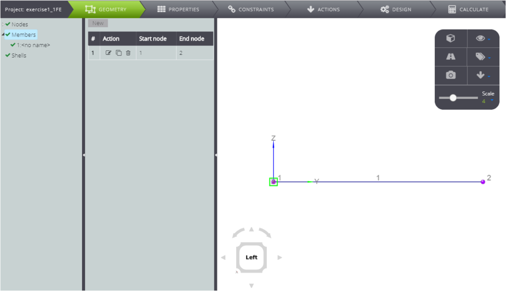
If you want to define a member on the grid, you can also define nodes and members at the same time, simply by clicking on the grid once to enter the start node and twice for the end node.
You have now defined the geometry of the cantilever beam! You can therefore attribute the properties of the section.
Properties
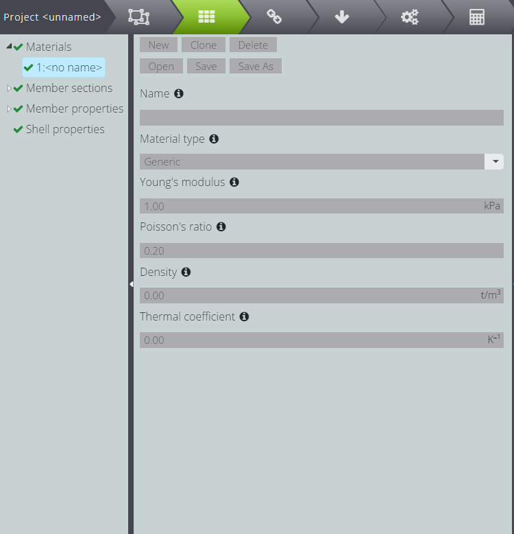
Click PROPERTIES in the Tab Bar.
Define the material.
- click on Materials in the Entity Tree
- move to the Data Panel and press New
- fill in the data as in the image below
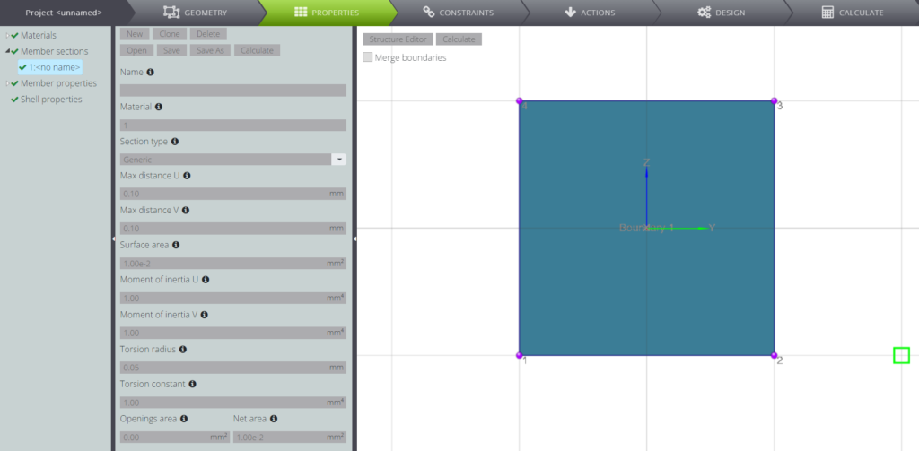
Now define the section:
- click on Member Sections in the Entity Tree
- click on New in the Data Panel
- fill in the fields as shown in the image below
- If you click on Section Editor, you can see your section take shape.
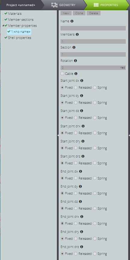
Then assign the properties to the member.
- click on Member Properties in the Entity Tree;
- click on New in the Data Panel;
- fill in the fields as shown in the following image.
Constraints
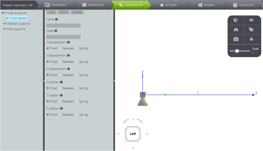
You are ready to enter the constraints! To impose a constraint on node one, start by pressing CONSTRAINTS on the Tab Bar. Then:
- click on Node supports in the Entity tree
- click on New in the Data Panel
- fill all fields as in the following image, with all levels of “Fixed” freedom
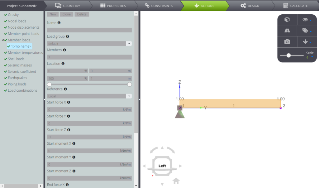
Now you are only missing the distributed load! To insert it, click on ACTIONS on the Tab Bar.
- move in the Entity tree and click on Member loads
- go to the Data Panel and press New
- enter the member number in the Member field
- enter the amount of load in the Start force Z and End force Z fields
Analysis & Results
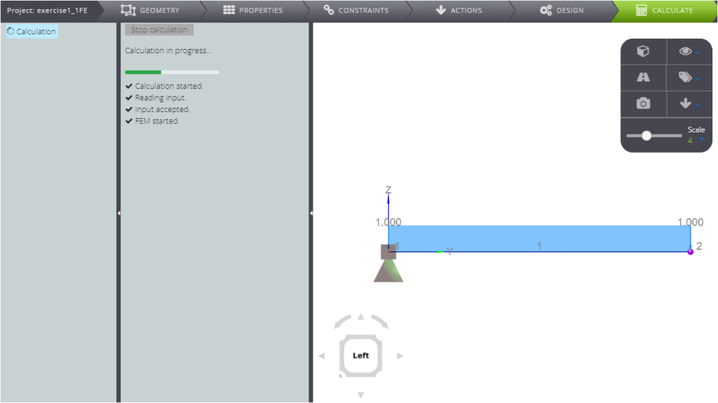
You have defined all the data of the problem, you are ready to launch the analysis!
Click the CALCULATE tab, go to the Data Panel and press Start calculation.
When the results are ready, go to the Entity tree and press 1:default: start scrolling the results!
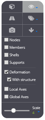
Remember that you can decide whether or not to see the deformed structure by selecting Deformation in the ToolBox.
READING THE RESULTS
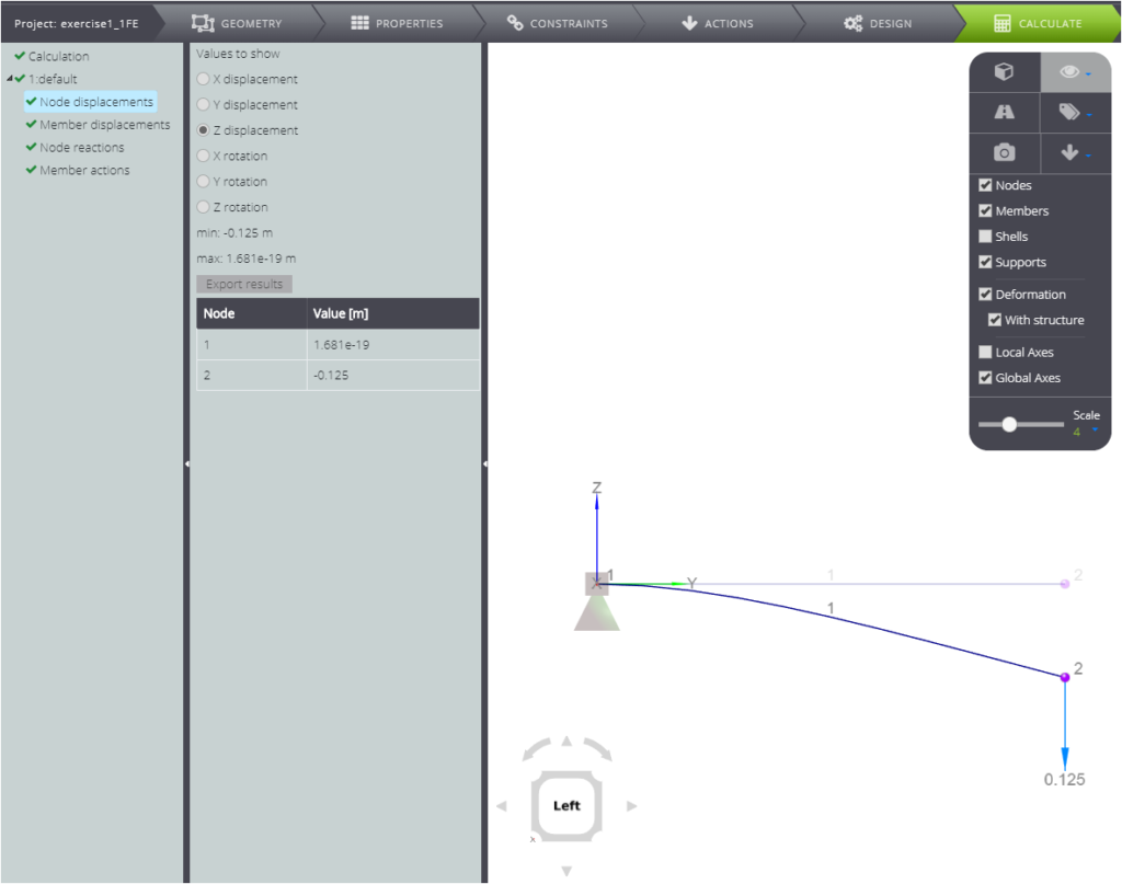
If you click on Node displacements, in the Data Panel you can select which component of the displacement or rotation to display.
The Data Panel will update a table showing the results.
You will see the representation of the displacements in Viewport 3D. The displacements are represented as vectors.
Below you can see for example the displacement of nodes in the Z direction.
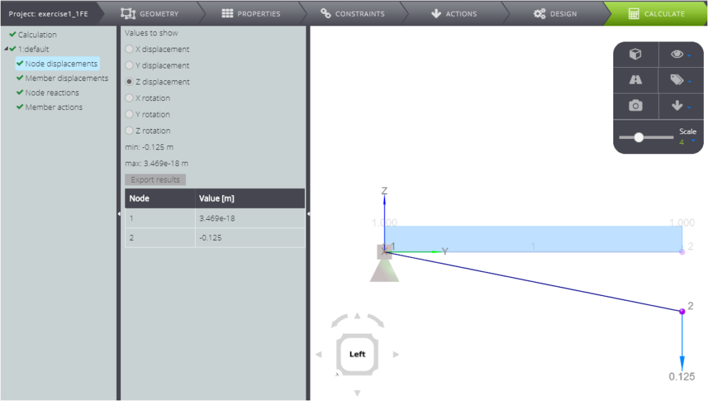
Here instead we show you the rotation around the X axis
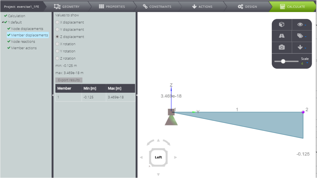
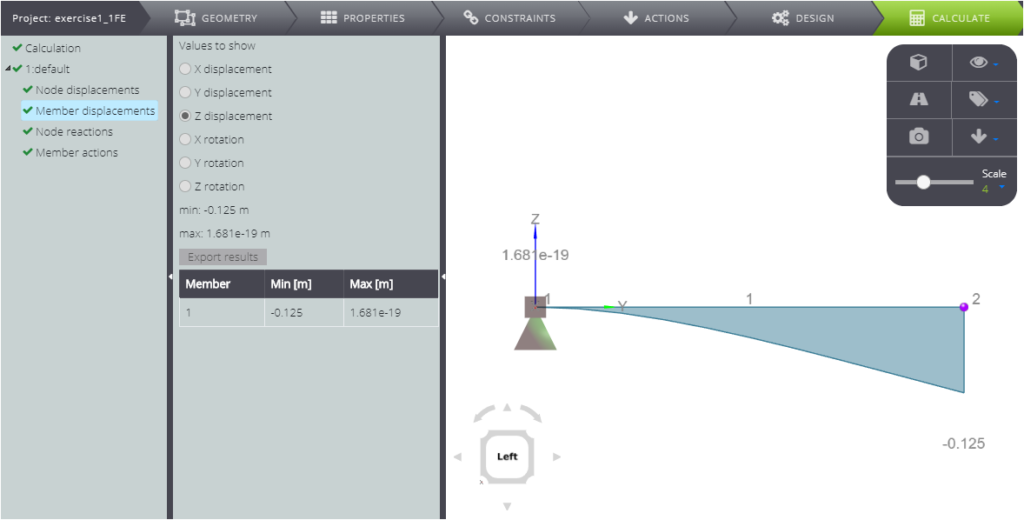
To view member displacement, press Member displacement in the Entity tree, then move to the Data Panel to select the displacement component to view.
Remember that the axes are those of the element’s local reference system.
You’ll see the results as a graph: for example, below are the displacements of the beam in the z direction.
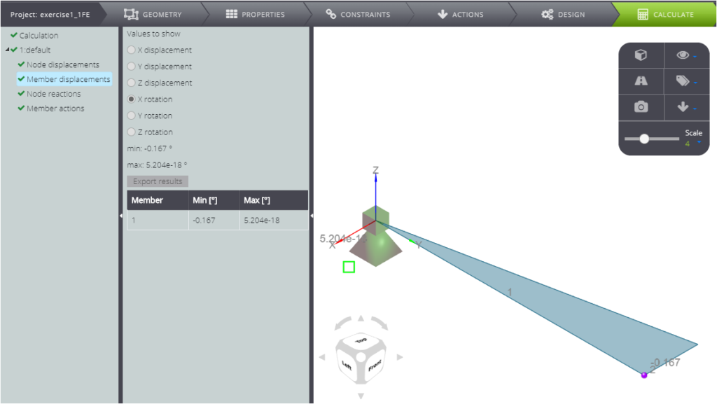
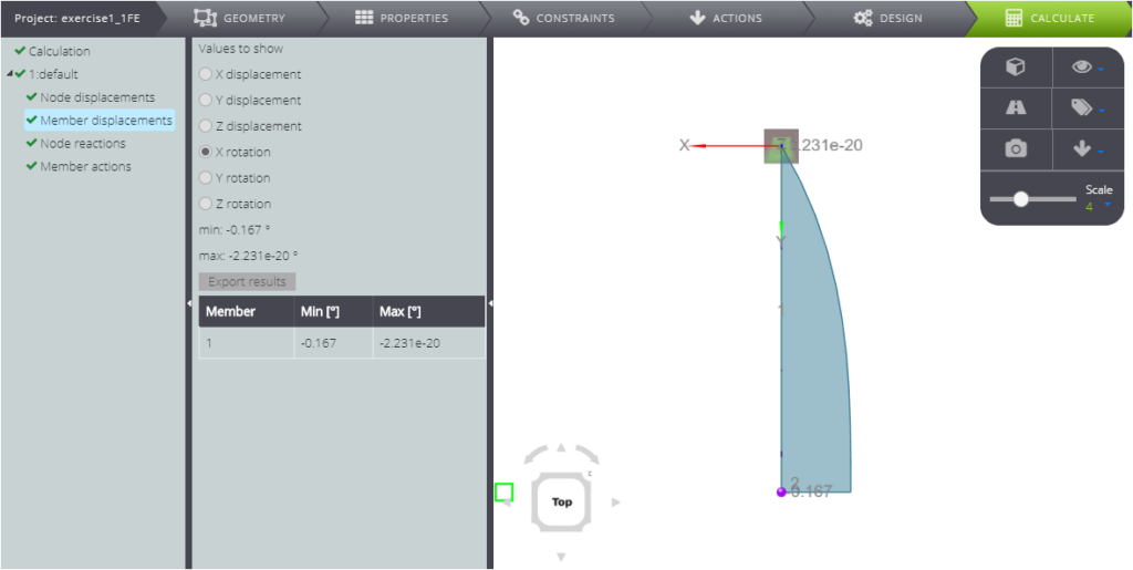
Below you can see the rotation around the x axis
Have you noticed that the shape of the results is not what you expect?
In this case it is because no subdivisions have been set for the model mesh. This means that it consists of a single element: the results are accurate only at the nodes. By refining the mesh, you’ll get the results in more points! We will see this later.
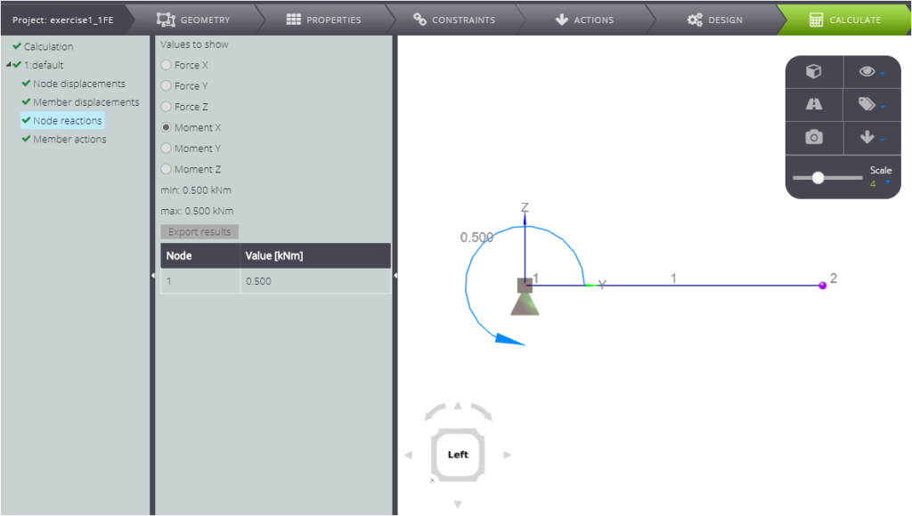
Continuing to scroll through the results, you find the nodal reactions by clicking on Node reactions in the Entity tree. Of course you can see both the forces…
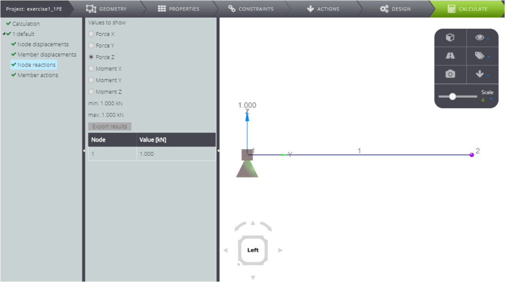
…and the bending moments!
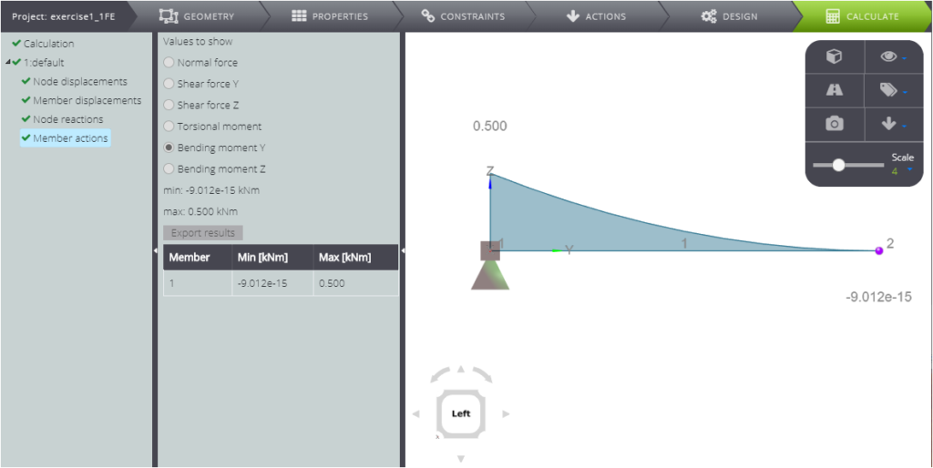
Lastly, by clicking on Member actions into the Entity tree, you will have at your disposal the diagrams of the stress parameters on the beam.
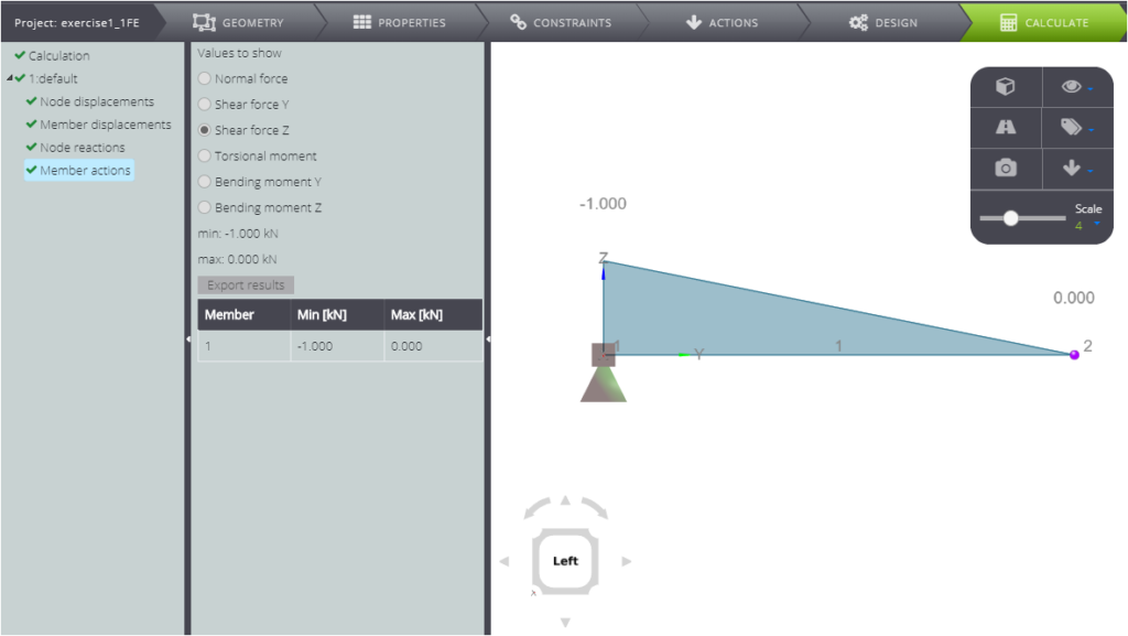
Above, see the shear force diagram, below see the bending moment diagram.
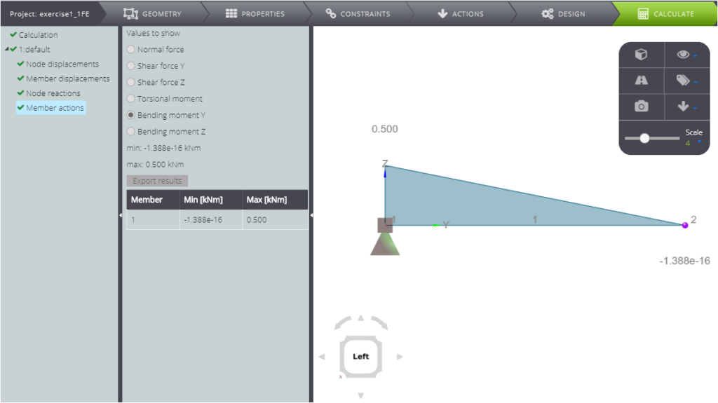
As with the deformed, you may have noticed that the shape of the internal forces diagrams is wrong. This is due to the discretization of the geometry!
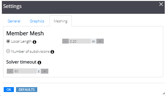
Meshing
To set it differently, go to the top bar and press Settings and then Meshing: a window like the one in the image below will open.
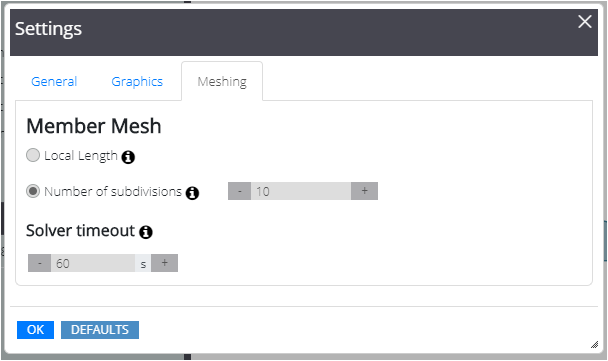
Then decide in how many parts to divide each element, as above, or the maximum length of each element that will compose the mesh, as below.
Launching the analysis again, you will see that the shape of the results is more refined!
Below you can see the deformed.
Here is a graph of the member’s Z-direction movements.
Below, the rotation around the x-axis.
And finally, the diagrams of the internal forces. Below, the bending moment diagram.
The cantilever beam is also discussed in our Verification manual! You will find the comparison between the numerical and analytical solution.