With this tutorial we show you how to create a plate with a surface support on the entire perimeter.
We also show you how to set up the analysis for the reinforcement design according to regulations.
You can already see the model!
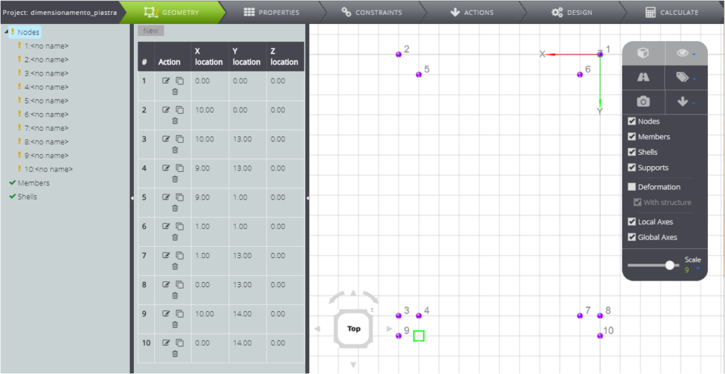
Start by clicking on GEOMETRY and creating the nodes, as in the figure below.
Then define the three plates as follows.
PropERTIES
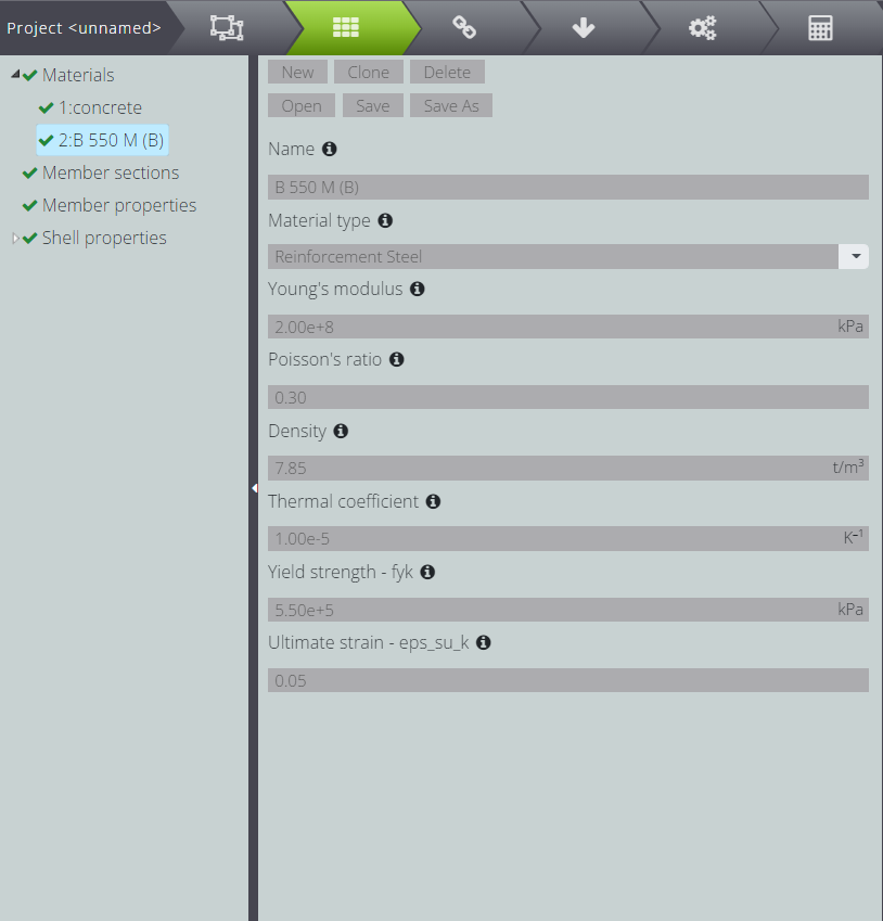
Create the materials in the PROPERTIES section.
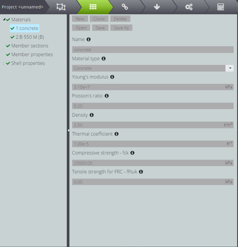
Above, see defined concrete and below reinforcement steel. It will be useful for your reinforcement design settings!
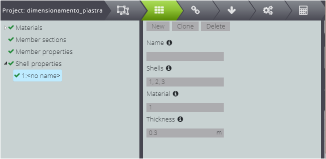
Attribute materials and thickness to shell elements.
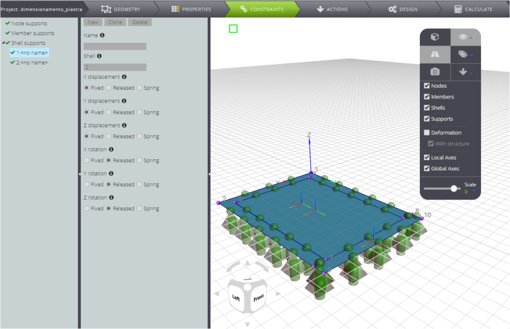
CONSTRAINTS
Lastly, attribute the constraints.
Block the movement of the shells that make up the support.
LOADS
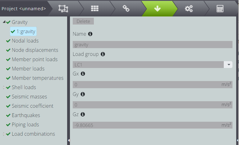
Assign loads by clicking on ACTIONS.
You can create the force of gravity
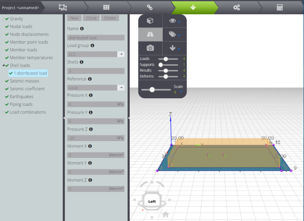
And assign a distributed load to the center plate.
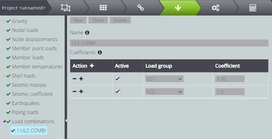
Define the ULS (Ultimate Limit State) load combination.
In the Load group menus you will find the names of the groups you assigned to the loads previously and in Coefficient you have to indicate the multiplicative coefficient.
RC design
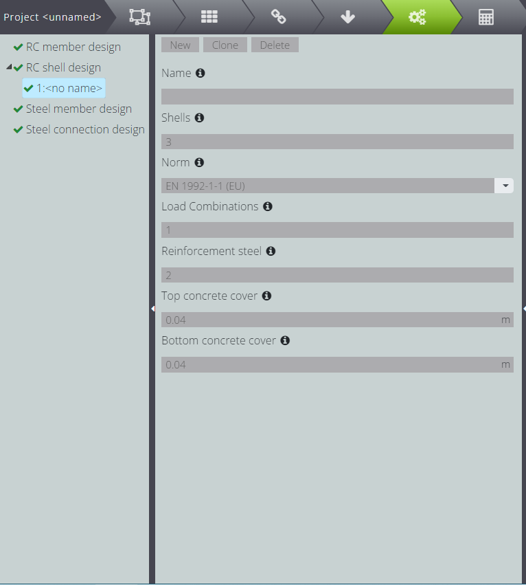
Under DESIGN enter all the necessary parameters for RC design.
- enter the number that identifies the shells you want to design
- choose the reference standard for the designing
- specifies the calculation combinations for which to perform the calculation
- write the number that identifies the reinforcement steel in Materials
- impose the distance between the upper flap and the center of gravity of the upper reinforcement
- repeat the last operation with the distance between the lower flap and the center of gravity of the lower reinforcement.
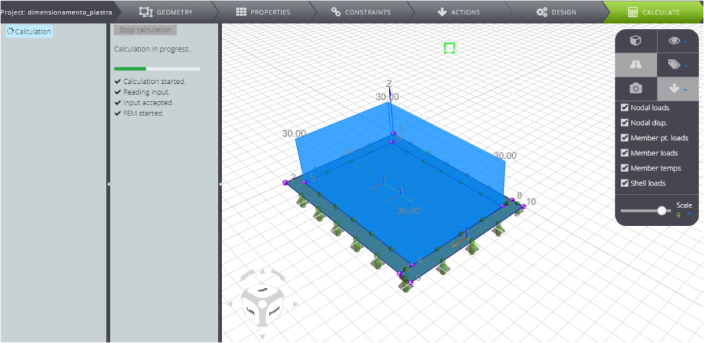
Now move to CALCULATE and launch the analysis!
RESULTS
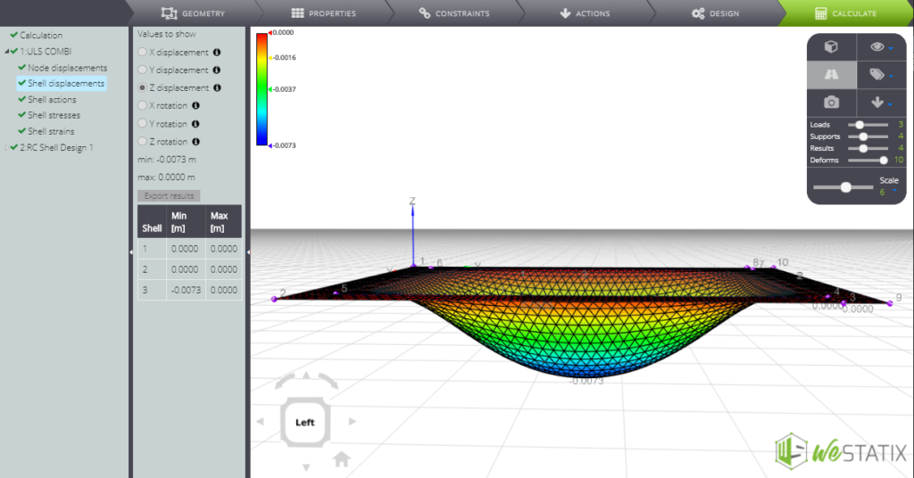
Find all the results of the static analysis for the load combination you created!
Below you see the movements in the Z direction and the deformed.
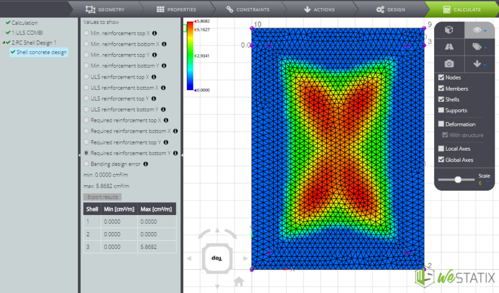
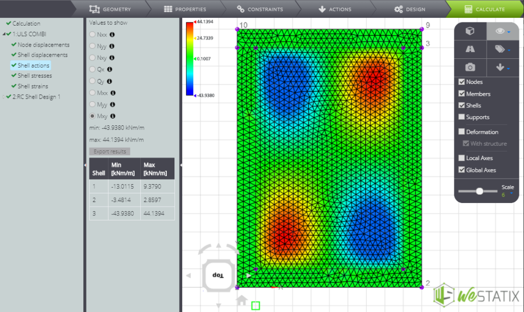
You can also read the trend of the internal stress parameters in the contour.
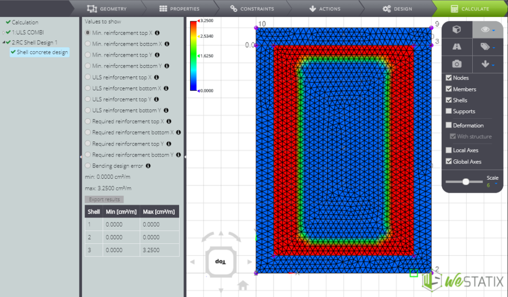
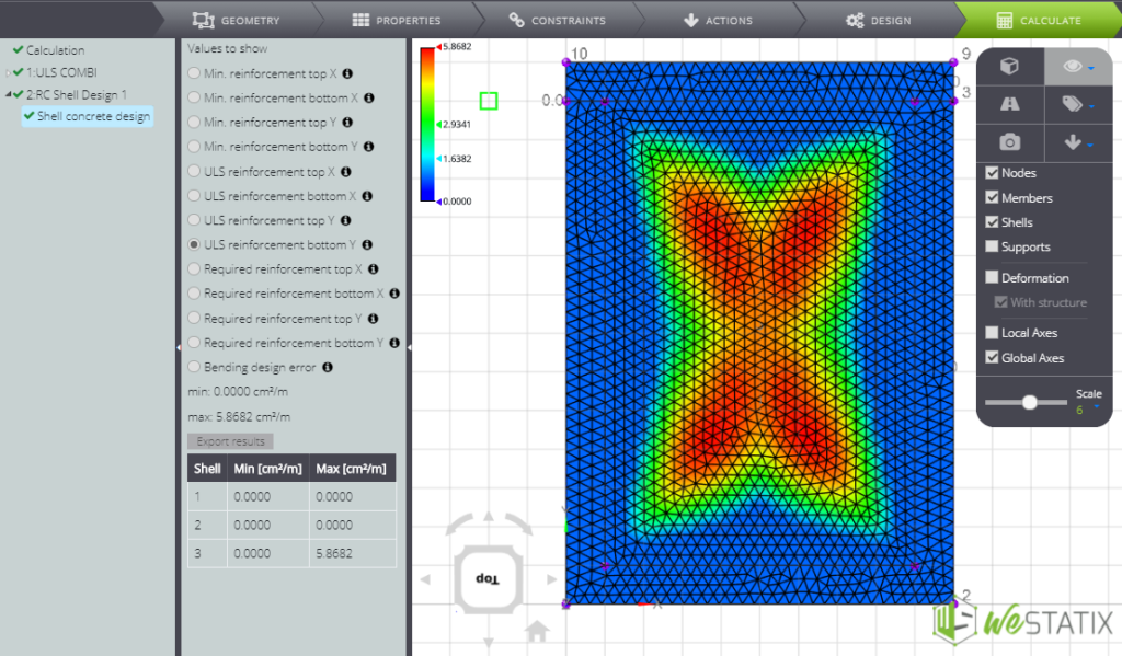
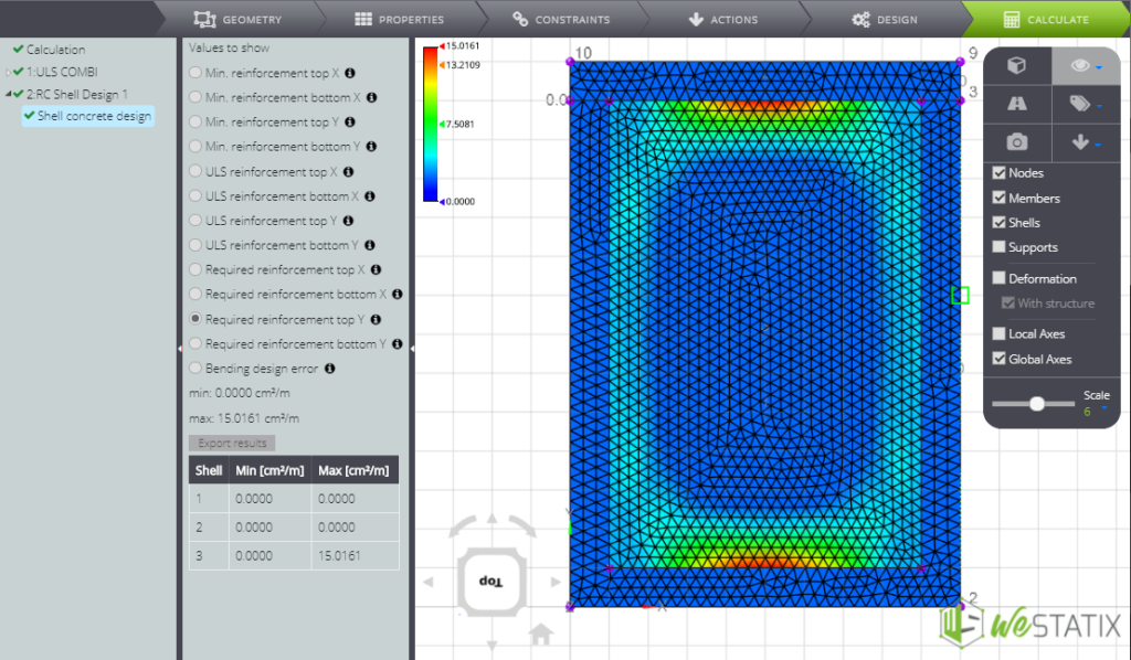
With regard to the results of reinforced concrete design, the following contours are representative of:
- minimum upper reinforcement in X direction
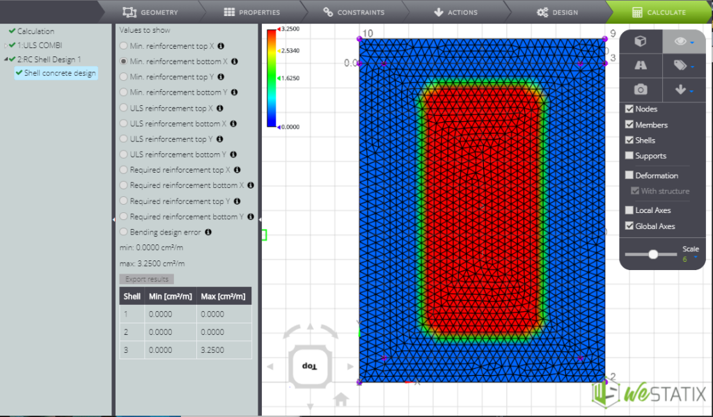
- minimum lower reinforcement in X direction
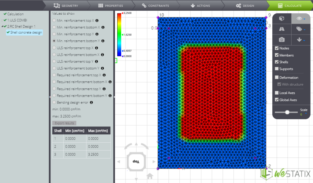
- minimum upper reinforcement in Y direction
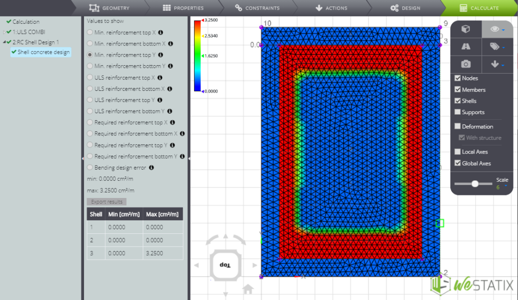
- minimum lower reinforcement in Y direction
- upper ULS reinforcement in X direction
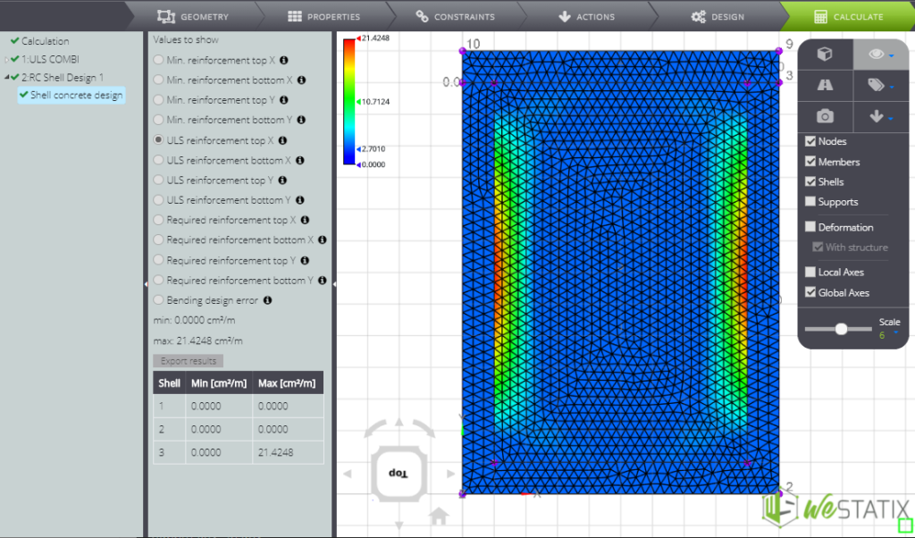
- lower ULS reinforcement in X direction
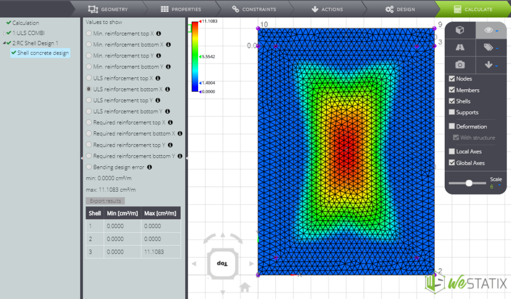
- upper ULS reinforcement in Y direction

- lower ULS reinforcement in Y direction
- upper required reinforcement in X direction

- Lower required reinforcement in X direction

- Upper required reinforcement in Y direction
- Lower required reinforcement in X direction