With this tutorial we show you how to model a simply supported square plate with side a and thickness h subject to uniform load q. If you want you can find the complete model already available in WeStatiX.
The problem data is listed below:
Side length \( a = 10 m \) ;
Thickness \( h = 0.3 m \) ;
Young’s modulus \( E = 10^8 kPa \) ;
Poisson’s ratio \( \nu= 0.3 \) ;
Pressure \( q = -10 kPa \).
Geometry
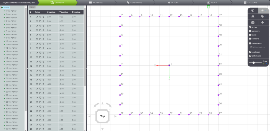
First of all, create the nodes. To create a denser mesh on the sides, define multiple knots along the same side. To do this you can use the graphical interface directly: set the grid spacing with a distance of one meter. At this point all you have to do is click twice on the grid points along the perimeter of the plate.
Create also a node in the center of the plate. This will be useful for reading the results
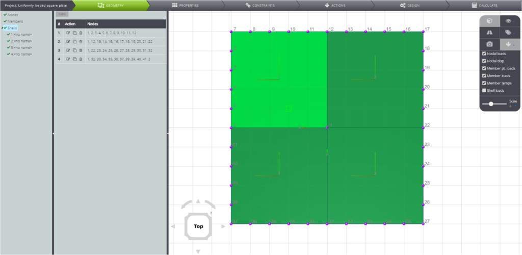
By joining the nodes by clicking on each of them, you create a shell. The mesh will be based on the four shells formed in this way.
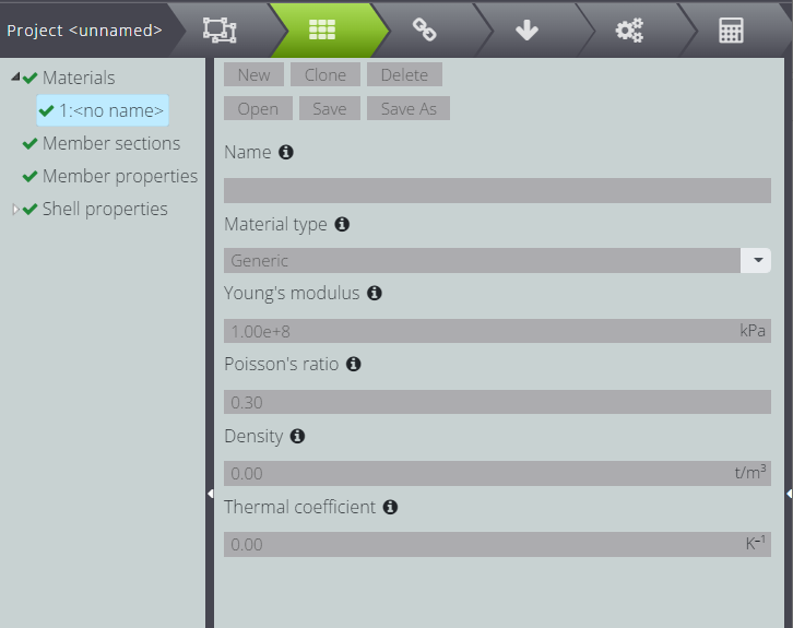
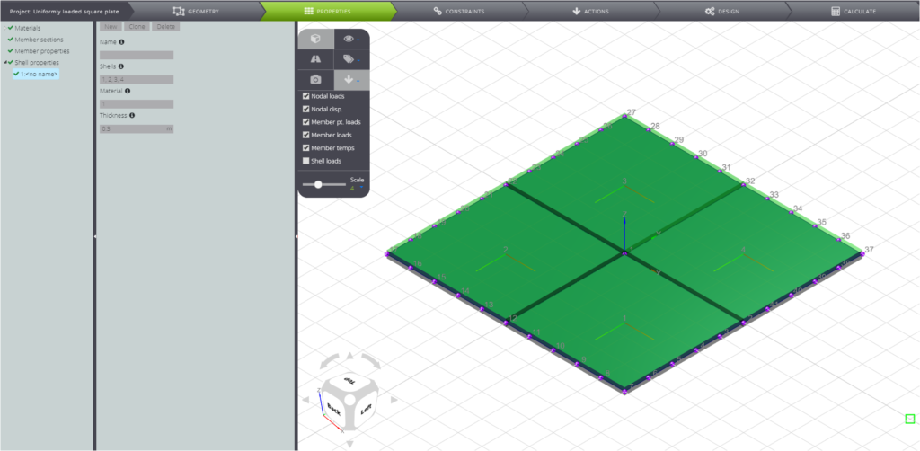
Now you can define materials and thicknesses by moving to PROPERTIES in the Tab Bar.
Properties
To define materials, crush Materials in the Entity tree. Press Parametric and enter the value of Young’s modulus and Poisson’s coefficient in the respective fields, as in the screenshot below.
In shell properties you attribute thickness and material to the four shells created previously.
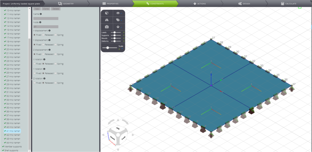
Constraints
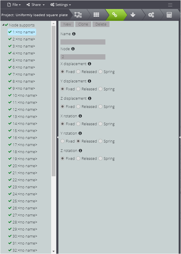
Now move to CONSTRAINTS and attribute the constraints to the nodes that define the perimeter of the plate. Press Node supports and then New.
First of all, concentrate on the nodes along the sides. On those for nodes that are on the sides parallel to the Y axis, free only the rotation around the axis itself.
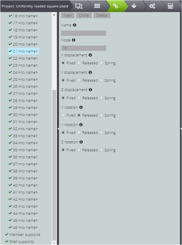
Then create the constraints for the nodes on the sides parallel to the X axis and free the rotation around X, similarly to what you did before.
Now for the four corners only fix the displacements and leave all the rotations free.
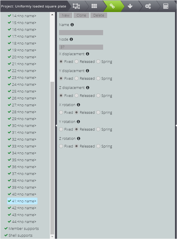
In the Viewport 3D you will see constraints on all nodes.
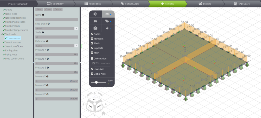
Loads
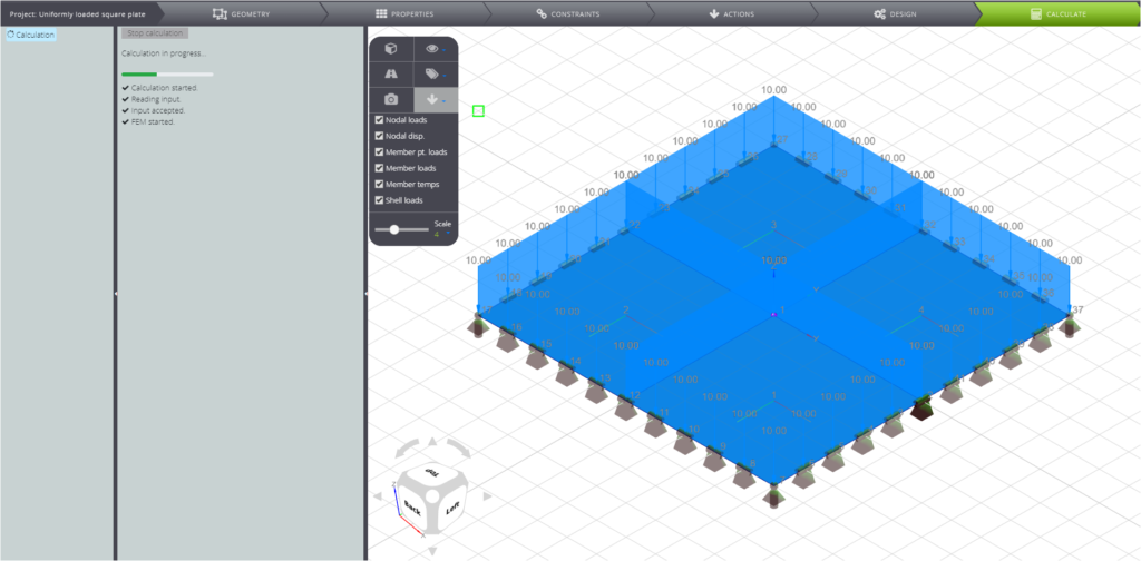
At this point only the distributed load is missing: select ACTIONS on the Tab Bar and click on Shell loads. For each shell fill in the fields in the second column as you can see in the screenshot below.
Lastly, go to CALCULATE and launch the analysis. The results of this problem have been validated: you can find them in our Validation Manual!