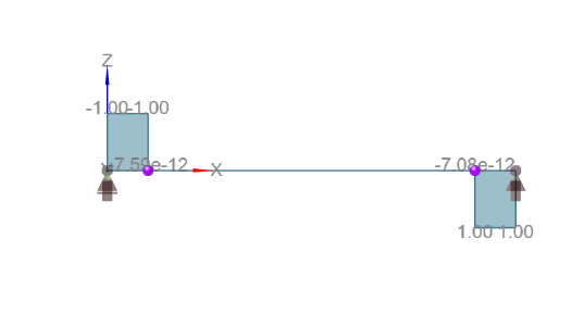
In order to test the RC member design, let’s consider the reinforced concrete rectangular beam represented below.
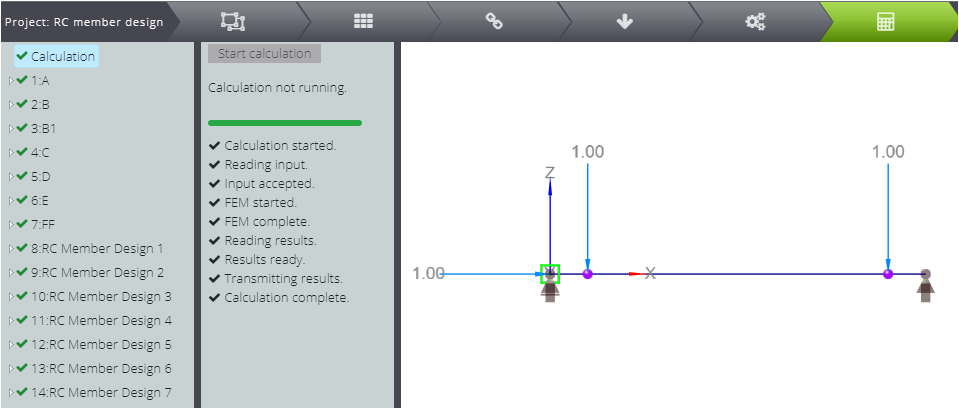
It’s a simply supported 10m long beam with two point loads located at the distance of 1m from the supports.
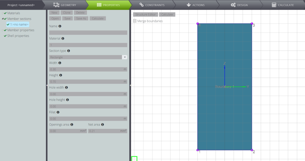
The cross section characteristics are presented in the following table.
| Description | Symbol | Value | UM | |
|---|---|---|---|---|
| Overall width of a cross-section | \(b\) | \(\) | 30,0 | cm |
| Height | \(h\) | \(\) | 70,0 | cm |
| Bottom concrete cover | \(c\) | \(\) | 50 | mm |
| Top concrete cover | \(c’\) | \(\) | 50 | mm |
| Effective depth of a cross-section | \(d\) | \(h-c\) | 65,0 | cm |
| \(z_S\) | \(h-c-c’\) | 60,0 | cm | |
| \(z_{s1}\) | \(h/2-c\) | 60,0 | cm | |
| \(z_{s2}\) | \(h/2-c’\) | 60,0 | cm |
You can also find the model in WeStatiX or learn how to build it thanks to our tutorial.
Results
Now, take a close look to the results: you can examine them for each load combination and for each RC member design case. They will be the linear combination of the following diagrams.
As you can see, the member 2 is never subjected to shear force. The design of the reinforced concrete beam section is therefore performed only for this member for the six cases shown in the table.
| CASE | A | B | C | D | E | F | ||
|---|---|---|---|---|---|---|---|---|
| Bending moment [kNm] | \(M_{Ed}\) | 500 | 1500 | 1000 | 1000 | 400 | 300 | |
| Axial force [kN] | \(N_{Ed} \) | 0 | 0 | 1000 | 1800 | 2000 | 2000 |
Here we focus on the RC member design results and we compare them with what we can obtain following the guidelines of the standard EN1992-1-1. [1]
The material parameters are listed in the table below.
| Description | Symbol | Formula | value | UM |
|---|---|---|---|---|
| Characteristic compressive cylinder strength of concrete at 28 days | \(f_{ck}\) | \(\) | 25.000 | kPa |
| Characteristic yield strength of reinforcement | \(f_{yk}\) | \(\) | 420.000 | kPa |
| Coefficient taking account of long term effects | \(\alpha_{cc}\) | \(\) | 1,00 | – |
| Partial factor for concrete | \(\gamma_c\) | \(\) | 1,50 | – |
| Partial factor for reinforcing or prestressing steel | \(\gamma_s\) | \(\) | 1,15 | – |
| Design value of concrete compressive strength | \(f_{cd}\) | \(\alpha_{cc} f_{ck}/\gamma_c\) | 16.670 | kPa |
| Design value for yield strength of reinforcement | \(f_{yd}\) | \(f_{yk}/\gamma_{s}\) | 365.220 | kPa |
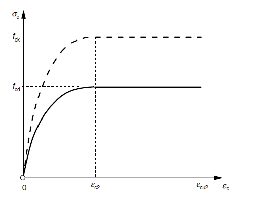
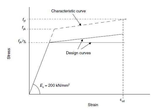
In the graphs you can see the stress-strain relationships for concrete and for reinforcement steel.
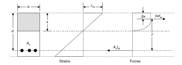
Given the material parameters and the section characteristics you can calculate the following parameters.
| \(x_{lim}\) | \(\frac{700 \cdot d}{f_{yd [MPa]}+700}\) | 42,71 | cm | |
| \(F_{cd,lim}\) | \(0,8095 \cdot x_{lim} \cdot b \cdot f_{cd}\) | 1.728,86 | kN |
They will help you to define various stress conditions on the cross sections.
CASE A
In the first case, the middle part of the beam is subjected to pure bending conditions.
| Bending moment | \(M_{Ed}\) | \(\) | 500 | kNm |
| Axial force | \(N_{Ed}\) | \(\) | 0 | kN |
In order to compute the reinforcement area you need to calculate the following parameter, as described in [1].
| Description | Symbol | Formula | value | UM |
|---|---|---|---|---|
| \(M_{S1}\) | \(M_{s1} =M_{Ed}\) | 500 | kNm | |
| Neutral axis depth | \(x\) | \(1,202\left(d-\sqrt{d^2-\frac{2,055 \cdot M_{s1}}{b\cdot f_{cd}}}\right)\) | 22,1 | cm |
| \(x<x_{lim}\) | ||||
| \(F_{cd}\) | \(0,8095 \cdot x \cdot b \cdot f_{cd}\) | 895,99 | kN | |
| \(M_{cd1}\) | \(F_{cd}\cdot(d-0,4160x)\) | 499,88 | kNm |
In this case the beam is singly reinforced and you can easily calculate the solution for the cross sectional area of reinforcement steel.
| ANALYTICAL | WSX | ERROR | |||
|---|---|---|---|---|---|
| Cross sectional area of reinforcement (bottom) [cm^2] | \(A_{s1}’\) | \(\frac{F_{cd}-N}{f_{yd}}\) | 24,53 | 24,54 | 0,04% |
The results for the RC member design are shown in the figure below.
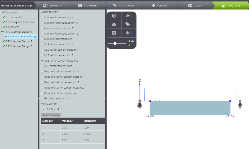
As it matches perfectly the results we got following the standard.
CASE B
As in the case A the Axial force is null, but the bending moment is bigger.
| Bending moment | \(M_{Ed}\) | \(\) | 1500 | kNm |
| Axial force | \(N_{Ed}\) | \(\) | 0 | kN |
This lead you to the following calculation.
| Description | Symbol | Formula | value | UM |
|---|---|---|---|---|
| \(M_{S1}\) | \(M_{s1} =M_{Ed}\) | 1500 | kNm | |
| Neutral axis depth | \(x\) | \(1,202\left(d-\sqrt{d^2-\frac{2,055 \cdot M_{s1}}{b\cdot f_{cd}}}\right)\) | – | cm |
| \(\sqrt{\cdot}<0\) | ||||
| Neutral axis depth | \(x\) | \(x=x_{lim}\) | 42,71 | cm |
| \(F_{cd}\) | \(0,8095 \cdot x \cdot b \cdot f_{cd}\) | 1.728,86 | kN |
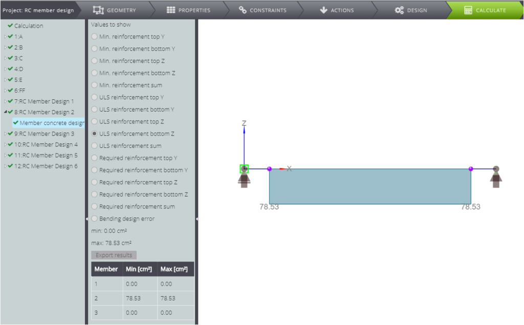
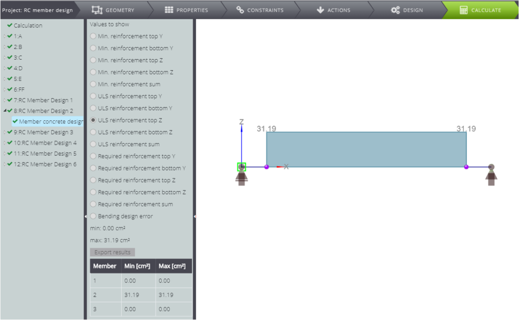
Given the bigger entity of the bending moment, in this case you will need to put a reinforcement area also on the top of the cross section. You can calculate the cross sectional area for bottom and top reinforcement and compare it with WeStatiX results.
| ANALYTICAL | WSX | ERROR | |||
|---|---|---|---|---|---|
| Cross sectional area of reinforcement (bottom) [cm^2] | \(A_{s1}\) | \(\frac{F_{cd}+A_{s2} \cdot f_{yd}-N}{f_{yd}}\) | 78,53 | 78,53 | 0,00% |
| Cross sectional area of reinforcement (top) [cm^2] | \(A_{s2}\) | \(\frac{M_{s1}-M_{cd1}}{f_{yd}\cdot z_s}\) | 31,19 | 31,19 | 0,00% |
As you can see, the two solutions match.
CASE C
In this case the cross section stress depends on the bending moment, but also on the axial force.
| Bending moment | \(M_{Ed}\) | \(\) | 1000 | kNm |
| Axial force | \(N_{Ed}\) | \(\) | 1000 | kN |
In order to compute the reinforcement area, you need to calculate parameters displayed in the table.
| Description | Symbol | Formula | value | UM |
|---|---|---|---|---|
| \(M_{S1}\) | \(M_{s1} =M_{Ed}+N_{Ed}\cdot z_{s1}\) | 1300 | kNm | |
| Neutral axis depth | \(x\) | \(1,202\left(d-\sqrt{d^2-\frac{2,055 \cdot M_{s1}}{b\cdot f_{cd}}}\right)\) | – | cm |
| \(\sqrt{\cdot}<0\) | ||||
| Neutral axis depth | \(x\) | \(x=x_{lim}\) | 42,71 | cm |
| \(F_{cd}\) | \(0,8095 \cdot x \cdot b \cdot f_{cd}\) | 1.728,86 | kN |
Now, as you did in the previouses case, you can calculate the reinforcement areas and compare it with the numerical results.
| ANALYTICAL | WSX | ERROR | |||
|---|---|---|---|---|---|
| Cross sectional area of reinforcement (bottom) [cm^2] | \(A_{s1}\) | \(\frac{F_{cd}+A_{s2} \cdot f_{yd}-N}{f_{yd}}\) | 42,02 | 42,01 | 0,02% |
| Cross sectional area of reinforcement (top) [cm^2] | \(A_{s2}\) | \(\frac{M_{s1}-M_{cd1}}{f_{yd}\cdot z_s}\) | 22,06 | 22,05 | 0,05% |
Also in this case WeStatiX solution for the design of a reinforced concrete beam is verified.
CASE D
Now let’s look at the stress status when you increase the axial force.
| Bending moment | \(M_{Ed}\) | \(\) | 1000 | kNm |
| Axial force | \(N_{Ed}\) | \(\) | 1800 | kN |
Unlike the previous case the compression force \(N > F_{cd,lim} \)
Again, calculate the following parameters.
| Description | Symbol | Formula | value | UM |
|---|---|---|---|---|
| \(M_{S1}\) | \(M_{Ed}+N_{Ed}\cdot z_{s1}\) | 1540 | kNm | |
| \(M_{S2}\) | \(M_{s2} =M_{Ed}-N_{Ed}\cdot z_{s2}\) | 460 | kNm | |
| Neutral axis depth | \(x\) | \(1,202\left(c’-\sqrt{c’^2-\frac{2,055 \cdot M_{s1}}{b\cdot f_{cd}}}\right)\) | – | cm |
| \(\sqrt{\cdot}<0\) | ||||
| Neutral axis depth | \(x\) | \(x=x_{lim}\) | 42,71 | cm |
| \(F_{cd}\) | \(0,8095 \cdot x \cdot b \cdot f_{cd}\) | 1.728,86 | kN |
And finally, compute the cross sectional areas for reinforcement.
| ANALYTICAL | WSX | ERROR | |||
|---|---|---|---|---|---|
| Cross sectional area of reinforcement (bottom) [cm^2] | \(A_{s1}\) | \(\frac{F_{cd}+A_{s2} \cdot f_{yd}-N}{f_{yd}}\) | 31,06 | 31,07 | 0,03% |
| Cross sectional area of reinforcement (top) [cm^2] | \(A_{s2}\) | \(\frac{M{s1}-M_{cd1}}{f_{yd}\cdot z_s}\) | 33,01 | 33,01 | 0,00% |
As you compare it with WeStatiX output from the module for the design of reinforced concrete beam, you can notice the values are the same.
CASE E
Now decrease the bending moment.
| Bending moment | \(M_{Ed}\) | \(\) | 400 | kNm |
| Axial force | \(N_{Ed}\) | \(\) | 2000 | kN |
In order to define the stress status, define the parameters listed in the table.
| Description | Symbol | Formula | value | UM |
|---|---|---|---|---|
| \(M_{S1}\) | \(M_{Ed}+N_{Ed}\cdot z_{s1}\) | 1000 | kNm | |
| \(M_{S2}\) | \(M_{s2} =M_{Ed}-N_{Ed}\cdot z_{s2}\) | -200 | kNm | |
| Neutral axis depth | \(x\) | \(1,202\left(c’-\sqrt{c’^2-\frac{2,055 \cdot M_{s1}}{b\cdot f_{cd}}}\right)\) | 41,0 | cm |
| \(x<x_{lim}\) | ||||
| Neutral axis depth | \(x\) | \(x=x_{lim}\) | 42,7 | cm |
| \(F_{cd}\) | \(0,8095 \cdot x \cdot b \cdot f_{cd}\) | 1.728,86 | kN |
You still need reinforcement area both on the top and on the bottom of the section. Calculate it as follows.
| \(\) | \(\) | ANALYTICAL | WSX | ERROR | |
|---|---|---|---|---|---|
| Cross sectional area of reinforcement (bottom) [cm^2] | \(A_{s1}\) | \(\frac{F_{cd}+A_{s2} \cdot f_{yd}-N}{f_{yd}}\) | 0,95 | 0,95 | 0,00% |
| Cross sectional area of reinforcement (top) [cm^2] | \(A_{s2}\) | \(\frac{M{s1}-M_{cd1}}{f_{yd}\cdot z_s}\) | 8,37 | 8,37 | 0,00% |
Also in this case the two solutions overlap perfectly.
CASE F
As you can read in the following table, compared to CASE D with the same axial force, the bending moment is smaller.
| Bending moment | \(M_{Ed}\) | \(\) | 300 | kNm |
| Axial force | \(N_{Ed}\) | \(\) | 2000 | kN |
When you calculate the following parameter, you can notice that as apposed to the previouses cases the neutral axis depth is bigger than \(x_{lim}\)
| Description | Symbol | Formula | value | UM |
|---|---|---|---|---|
| \(M_{S1}\) | \(M_{Ed}+N_{Ed}\cdot z_{s1}\) | 900 | kNm | |
| \(M_{S2}\) | \(M_{s2} =M_{Ed}-N_{Ed}\cdot z_{s2}\) | -300 | kNm | |
| Neutral axis depth | \(x\) | \(1,202\left(c’-\sqrt{c’^2-\frac{2,055 \cdot M_{s1}}{b\cdot f_{cd}}}\right)\) | 48,6 | cm |
| \(x>x_{lim}; x<h\) | ||||
| \(F_{cd}\) | \(0,8095 \cdot x \cdot b \cdot f_{cd}\) | 1.968,82 | kN |
This implies that only the top reinforcement area is needed.
| ANALYTICAL | WSX | ERROR | |||
|---|---|---|---|---|---|
| Cross sectional area of reinforcement (top) [cm^2] | \(A_{s2}’\) | \(\frac{N-F_{cd}}{f_{yd}}\) | 0,85 | 0,85 | 0,00% |
Again, WeStatiX results match the analytical ones.
[1] Skriptum zur Vorlesung BETONBAU 1 nach EC 1992-1-1, Technische Universität Wien, Institut für Tragkonstruktionen – Herausgegeben von Prof. Dr.-Ing. Johann KOLLEGER